
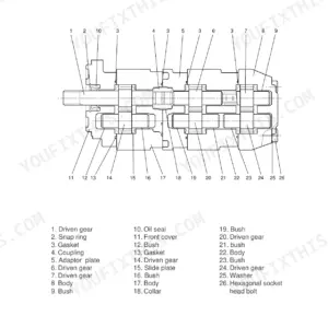
Part of the Hyundai Repair Manuals.
Looking for the Hyundai Robex 15-7 service manual PDF your dealer won't hand over? This factory manual runs 119 pages and covers the Robex 15-7 hydraulic excavator from the main pump to the crawler assembly. Hydraulic circuit diagrams, an electrical wiring section with failure-and-remedy charts, exploded views of the control valve, slew motor, and travelling motor, and a troubleshooting section that walks the travelling, slewing, boom, and swing systems. Standard-of-maintenance tables cover the attachment, idler, sprocket, and track rollers. Set the main relief valve to 18.6 MPa (190 kgf/cm2) and tighten 1/4 PF hose fittings to 27 to 30 N-m. No more chasing hydraulic faults with a gauge and a hunch. Bookmarked with a full text layer, so you can search any spec and jump straight to the Control Valve or Troubleshooting section.
What's Inside This Hyundai Robex 15-7 Manual
| System | Pages | Key Topics |
|---|---|---|
| Precautions on Maintenance | 6 | Correct Operation, Safety Check, Preparation, Disassembly, Repair, Assembly |
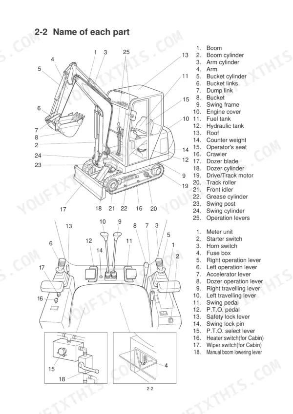
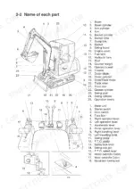
| Outline | 7-24 | Location of Serial No., Name of Each Part, Dimensions and Specification, Weight List, Oil and Grease Supply Points, List of Supply Oil and Grease, When to Repair |
| Attachment | 25-32 | Standard of Maintenance, Inspection and Adjustment |
| Engine | 33-36 | Specification, Performance Curve |
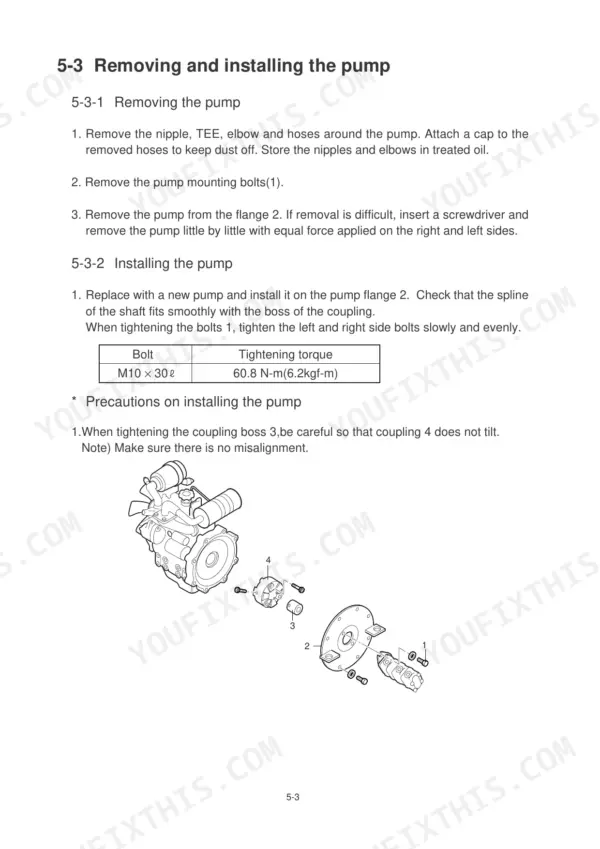
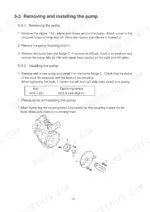
| Main Pump | 37-42 | Specification, Structure, Removing and Installing the Pump, Performance Test |
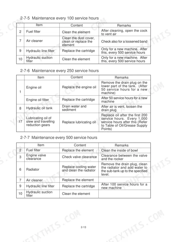
| Hydraulic Oil Filter | 43-48 | Installation, Maintenance Procedure |
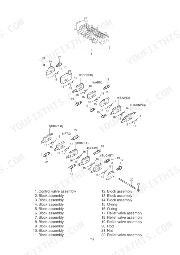
| Control Valve | 49-56 | Specification, Disassembly and Assembly, Structure of the Relief Valve, Precautions for Handling |
| Joystick | 57-60 | Specification, Structure |
| Slew Motor | 61-66 | Specification, Structure, Slew Bearing and Slew Case, Measuring Natural Slew Distance, Measuring Over-Slew Distance, Measuring Slewing Time |
| Travelling Motor | 67-72 | Specification, Structure, Operation, Handling the Travelling Motor, Measuring Idling and Travelling Time, Inspection and Adjustment |
| Hydraulic Cylinder | 73-78 | Structure, Disassembly and Assembly, Assembly |
| Swivel Joint | 79-82 | Specification and Structure, Structure, Disassembly and Assembly |
| Crawler | 83-90 | Structure and Operation, Standard of Maintenance, Disassembly and Assembly |
| Spring Case and Grease Cylinder | 91-94 | Structure, Disassembly and Assembly |
| Idler | 95-96 | Standard of Maintenance |
| Sprocket | 97-100 | Disassembly and Assembly, Standard of Maintenance |
| Track Roller | 101-102 | Standard of Maintenance |
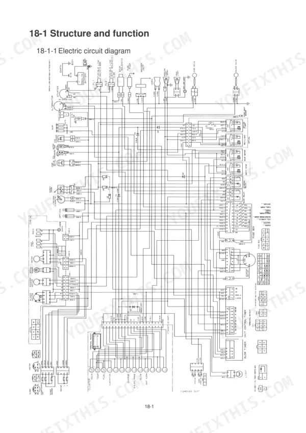
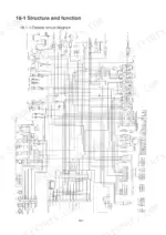
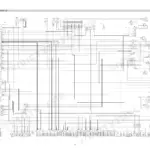
| Electrical Equipment | 103-106 | Structure and Function, Failure and Remedy |
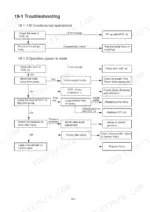
| Troubleshooting | 107-119 | Travelling System, Slewing System, Boom System, Swing System |
Quick Reference Specifications
| Specification | Value | Page |
|---|---|---|
| Tightening torque for M6 bolts (8.8 grade) | 12.5 N-m | p. 19 |
| Tightening torque for M8 bolts (8.8 grade) | 30 N-m | p. 19 |
| Tightening torque for PF screw hose fitting (1/4 size) | 27~30 N-m | p. 19 |
| Tightening torque for PF screw hose fitting (3/8 size) | 47~52 N-m | p. 19 |
| Main relief pressure | 18.6MPa (190kgf/cm2) | p. 50 |
| Main relief valve tightening torque (Cap nut) | 29.4N-m (3.0kg-m) | p. 55 |
| Port relief pressure | 20.6MPa (210kgf/cm2) | p. 50 |
| Port relief valve tightening torque (Cap nut) | 29.4N-m (3.0kgf/m) | p. 55 |
| Line filter tightening torque | 19.6Nm (2kgf/m) | p. 45 |
| Line filter filtration accuracy | 10µ | p. 45 |
| Total amount of hydraulic oil | 24 l | p. 47 |
| Tightening torque of the cartridge valve | 183 to 206 N-m | p. 93 |
Hyundai Robex 15-7 Common Problems This Manual Covers
Hyundai Robex 15-7 boom, arm, and bucket all weak, low hydraulic force on every function
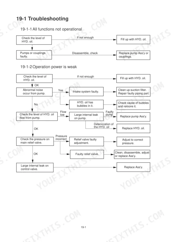
Check hydraulic oil level first, then test main relief pressure against the 18.6 MPa (190 kgf/cm2) spec on page 50. Follow the weak-power chart on page 108 to rule out pump noise and internal leaks. Adjust the relief valve and torque the cap nut to 29.4 N-m per page 55.
Manual Section: Operation Power is Weak p. 108Boom drops slowly or bucket creeps down with controls in neutral and engine running
Test the port relief valve against the 20.6 MPa (210 kgf/cm2) setting on page 50. If pressure holds, suspect internal cylinder leakage: disassemble per the hydraulic cylinder procedure on page 73 and replace the piston seals. Reinstall the relief valve at 68.6 N-m and torque the cap nut to 29.4 N-m.
Manual Section: Hydraulic Cylinder p. 73Hydraulic oil overheats after an hour of digging, all functions turn slow and spongy
Drain and refill with clean hydraulic oil; total system capacity is 24 L per page 47. Replace the line filter and tighten it to 19.6 N-m as shown on page 45; a clogged element opens the 0.15 MPa bypass and sends unfiltered hot oil back to the tank. Inspect the suction hose for kinks before restarting.
Manual Section: Hydraulic Oil Filter p. 47Machine pulls to one side, left track slow or stalls under load
Swap the travel hoses at the swivel joint to see if the fault follows the circuit; if it does, inspect the swivel joint seals per page 79. If the fault stays with the track, pull the travelling motor per page 67 and refill the case with 250 cc of lubricating oil, listed on page 21.
Manual Section: Travelling Motor p. 67No response from boom, arm, bucket, or slew, engine runs fine and travel works
Verify the safety lock lever is fully down and pilot pressure reaches the joysticks. Remove and clean the pilot filter, which screens to 31 microns, and retighten it to 58.8 to 78.5 N-m per page 46. Check the solenoid valve fuse and joystick wiring before condemning the control valve on page 49.
Manual Section: No Operation on Boom, Arm, Bucket, and Slewing p. 109Frequently Asked Questions
What are the replacement specifications for the main relief valve?
The main relief pressure for P1, P2, and P3 is 18.6 MPa (190 kgf/cm²) at 14.5 L/min. For port relief valves on A2, B2, A8, and B8, the pressure is 20.6 MPa (210 kgf/cm²) at 5 L/min. p. 50
What is the tightening torque for the main machine bolts and nuts?
The tightening torque depends on the bolt size and material grade. For an M10 bolt of grade 8.8, the torque is 62 N-m; for grade 10.9, it is 72 N-m; and for grade 12.9, it is 80 N-m. p. 18
What is the total hydraulic oil capacity for the system?
The total amount of hydraulic oil required for the system is 24 liters. p. 47
What is the standard sag for the fan belt?
The fan belt should be checked and adjusted to have a sag of 10 to 12 mm at the center. p. 17
What is the tightening torque for the travelling motor cartridge valve?
The tightening torque for the cartridge valve on the adjust cylinder is 183 to 206 N-m. p. 93
How quickly can I access this Hyundai Robex 15-7 manual after buying?
A 119-page Service Manual in searchable PDF format, available the moment you complete checkout. View on computer, tablet, or phone, with no shipping wait.
Can I print specific sections of this Hyundai Robex 15-7 Service Manual?
Yes. Print the sections you need to take out to the shop for your own use. Standard letter or A4 paper works.








Reviews
There are no reviews yet.