
Part of the Hyundai Repair Manuals.
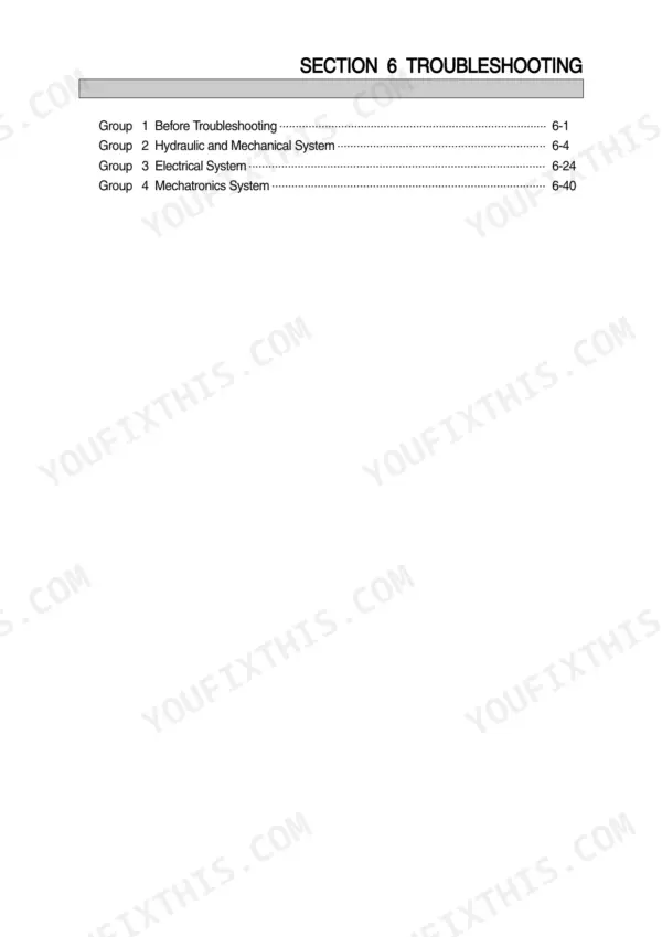
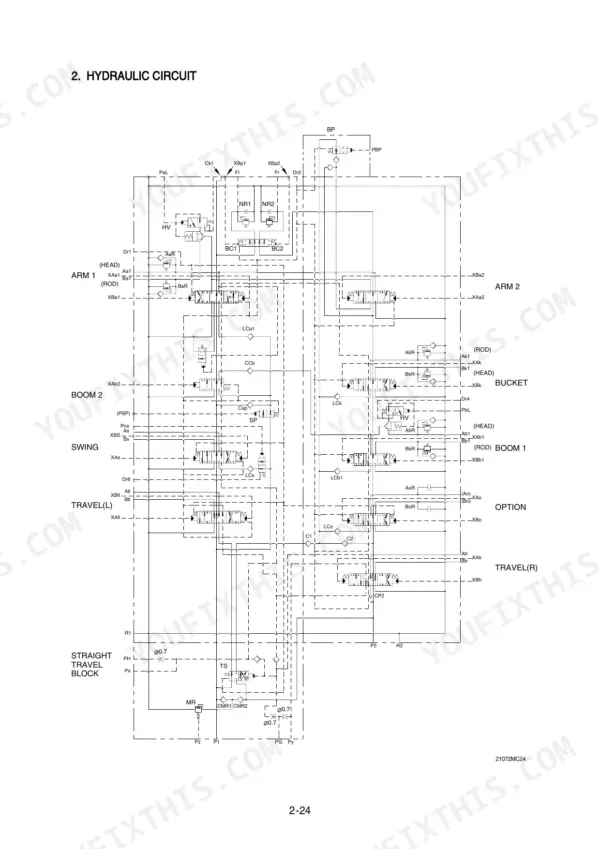
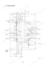
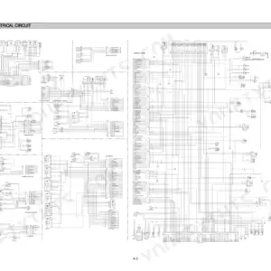
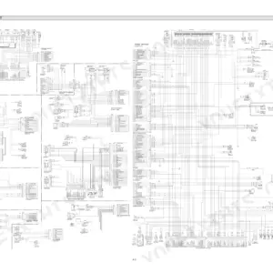
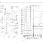
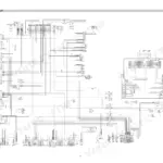
Your Hyundai Robex 210LC-7H just met its match: this 550-page Shop Manual PDF covers the crawler excavator end to end, Long Reach variant included. Inside: full electrical circuit diagrams with connector pinouts, hydraulic schematics tracing main and pilot circuits, and a Mechatronics section that decodes the self-diagnostic system, mode selection, and EPPR valve. You also get step-by-step disassembly procedures for the pump device, main control valve, swing device, travel device, and undercarriage, plus mounting torque tables for every system. Set the main relief valve to 330 kgf/cm2 (4694 psi), 360 kgf/cm2 (5120 psi) in power boost, and hold track roller shaft-to-bushing clearance between 0.39 and 0.476 mm. Your machine is down; forum threads won't lift it. Bookmarked with a full text layer, so you can search any spec and read it right at the excavator.
What's Inside This Hyundai ROBEX 210LC-7H Manual
| System | Pages | Key Topics |
|---|---|---|
| General | 4-31 | Safety Hints, Specifications |
| Structure and Function | 32-121 | Pump Device, Main Control Valve, Swing Device, Travel Device, Rcv Lever, Rcv Pedal |
| Hydraulic System | 122-153 | Hydraulic Circuit, Main Circuit, Pilot Circuit |
| Electrical System | 154-203 | Component Location, Electrical Circuit, Electrical Component Specification |
| Mechatronics System | 204-246 | Mode Selection System, Automatic Deceleration System, Engine Control System |
| Maintenance Standard | 303-337 | Operational Performance Test, Major Components, Track and Work Equipment |
| Disassembly and Assembly | 338-526 | Precaution, Tightening Torque, Pump Device, Main Control Valve, Swing Device, Travel Device, Rcv Lever, Turning Joint |
| Component Mounting Torque | 527-550 | Introduction Guide, Engine System, Electric System, Undercarriage, Structure, Work Equipment |
Quick Reference Specifications
| Specification | Value | Page |
|---|---|---|
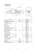
| Main pump maximum pressure | 330kgf/cm2 (4694psi) | p. 23 |
| Main pump power boost pressure | 360kgf/cm2 (5120psi) | p. 23 |
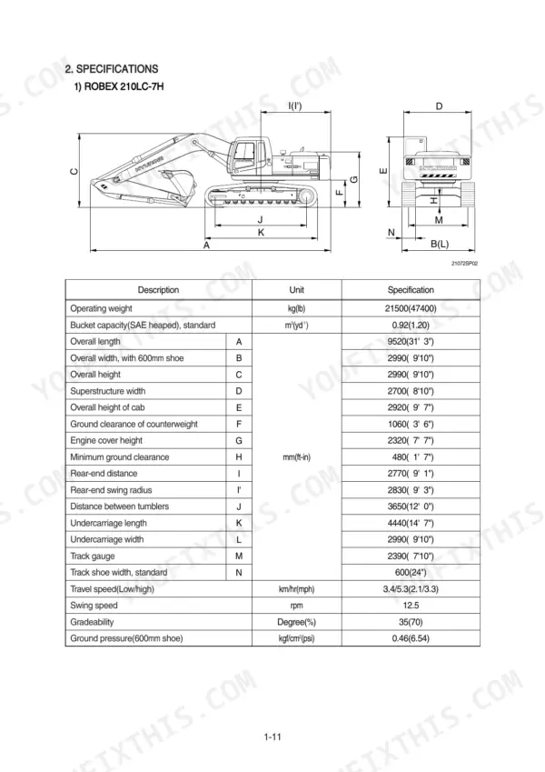
| R210LC-7H 600mm shoe ground pressure | 0.46kgf/cm2 (6.54psi) | p. 25 |
| R210LC-7H 700mm shoe ground pressure | 0.40kgf/cm2 (5.69psi) | p. 25 |
| Track roller clearance between shaft and bushing | 0.39 to 0.476 mm | p. 332 |
| Track roller side clearance of roller | 0.2 to 1.2 mm | p. 332 |
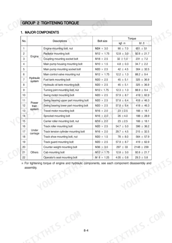
| Engine mounting bolt, nut | 90 ± 7.0 kgf·m | p. 342 |
| Radiator mounting bolt | 12.8 ± 3.0 kgf·m | p. 342 |
| Operating weight | 21500 kg | p. 15 |
| Swing speed | 12.5 rpm | p. 28 |
| Engine oil quantity | 16.3 L | p. 27 |
| Swing motor relief pressure | 240 kgf/cm2 | p. 28 |
Hyundai ROBEX 210LC-7H Common Problems This Manual Covers
Hyundai Robex 210LC-7H hydraulic functions slow and weak, pump whining with cavitation noise under load
Check hydraulic oil level in the sight gauge first, then pull the return filter and tank breather; a plugged breather starves the pump and makes it growl. Test main pump output against the 330 kgf/cm2 (4694 psi) spec on page 23, then work the noise and flow checks starting.
Manual Section: Hydraulic and Mechanical System Troubleshooting p. 23Hydraulic oil temperature gauge climbs into the red zone after an hour of normal digging
Clean the oil cooler core with compressed air from the fan side and check fan belt tension before condemning the pump. Verify oil level, then measure pump case drain pressure; a reading above the case drain limit in the hydraulic system section means internal wear is dumping heat into the oil.
Manual Section: Hydraulic and Mechanical System Troubleshooting p. 126Boom, arm, and bucket respond slowly or jerk when feathering the control levers
Check pilot pressure at the remote control valve; compare it against the pilot circuit settings in the hydraulic system section on page 127. Replace the pilot line filter if pressure drops under load, then retest each function.
Manual Section: Hydraulic System p. 127Tracks slip under load, machine throws a track on side slopes, rollers wearing fast
Measure track sag mid-span and adjust tension at the grease cylinder before buying parts. Inspect the rollers; shaft-to-bushing clearance beyond 0.39 to 0.476 mm on page 332 means the roller is done. Retorque loose track shoe bolts to the value in the torque table on page 342.
Manual Section: Maintenance Standard p. 332Swing is sluggish both directions and upper structure drifts when stopping on a grade
Test swing motor relief pressure; it should hold 240 kgf/cm2 (3414 psi) per page 24. Time a full rotation against the 12.5 rpm spec on page 28. If relief pressure is low, adjust or replace the relief valve and check the swing logic valve bolts against the tightening torque chart.
Manual Section: Hydraulic and Mechanical System Troubleshooting p. 28Frequently Asked Questions
How do I clear recorded error codes on a Hyundai ROBEX 210LC-7H?
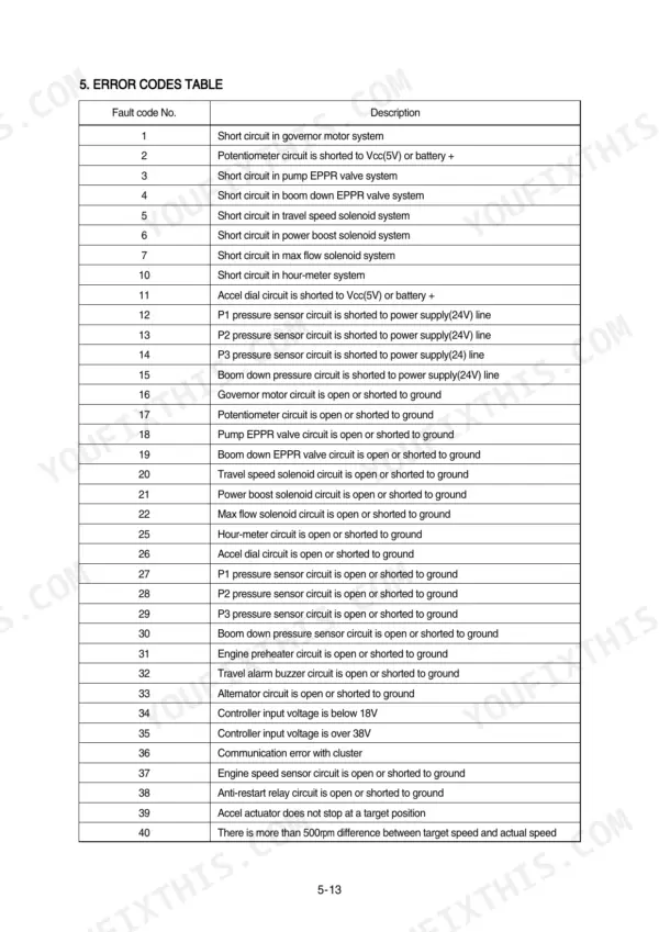
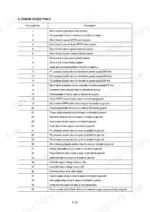
To delete all recorded error codes, select the recorded error (TIME Er) display on the cluster. Press the engine and select switch simultaneously for 2 seconds or more. The display will change to 'TIME Er : 00', indicating that the CPU controller has deleted all recorded error codes from the memory. p. 216
What is the tightening torque for the engine mounting bolts on a Hyundai ROBEX 210LC-7H?
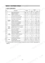
The tightening torque for the engine mounting bolts and nuts (M24 x 3.0) is 90 ± 7.0 kgf·m (651 ± 51 lbf·ft). p. 342
What is the procedure for bleeding air from the hydraulic pump after installation?
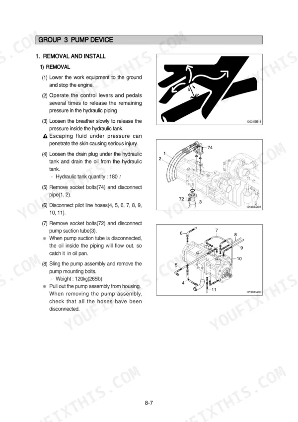
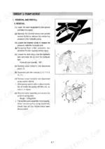
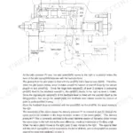
After installing the pump, remove the air vent plug(s) (2EA). Tighten the plug lightly, start the engine, and run it at low idling until oil comes out from the plug. Finally, tighten the plug fully. p. 346
What is the standard clearance for the track roller shaft and bushing?
The standard clearance for the track roller shaft and bushing is 0.39 to 0.476 mm, with a clearance limit of 2.0 mm. p. 332
What is the tightening torque for the main pump mounting socket bolts?
The tightening torque for the main pump mounting socket bolts (M20 x 2.5) is 42 ± 4.5 kgf·m (304 ± 32.5 lbf·ft). p. 342
What format is this Hyundai Robex 210LC-7H manual in?
Instant PDF download. You get the full 550-page searchable Shop Manual immediately after payment. Open it on your laptop, tablet, or phone right in the shop.
Is this Hyundai Robex 210LC-7H manual print-friendly?
Yes. Print individual pages or full chapters for your own shop use, on letter or A4 paper.






Reviews
There are no reviews yet.