
Part of the Hyundai Repair Manuals.
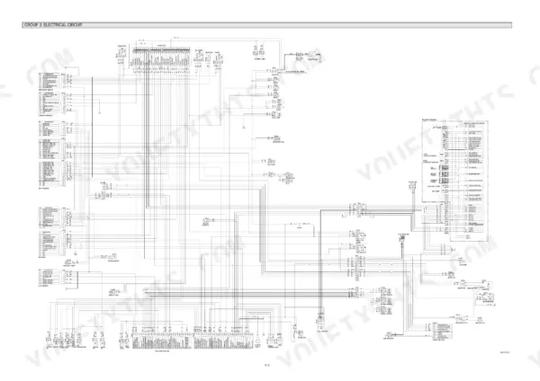
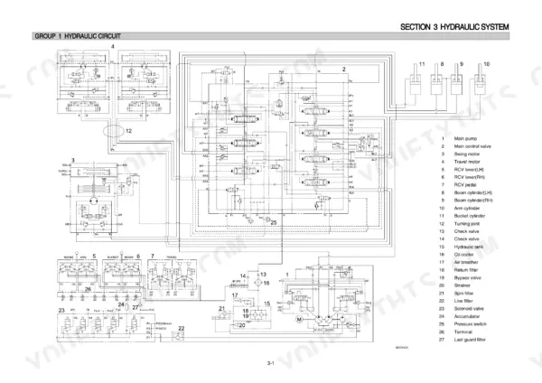
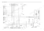
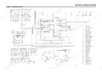
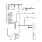
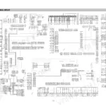
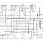
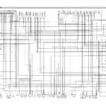
Every one of the 586 pages in this Hyundai R360LC-7 Shop Manual PDF was written to put your crawler excavator back to work. Inside: full hydraulic circuit schematics covering main and pilot circuits, complete electrical wiring diagrams with connector pinouts, and a troubleshooting section that walks the mechatronics self-diagnostic system fault by fault. You also get step-by-step disassembly and assembly procedures for the main pump, control valve, swing and travel devices, plus mounting torque tables for every system on the machine. Check that the bypass relief valve opens at 1.5 kgf/cm2 (21 psi), and confirm the 12V, 160Ah battery is feeding that Delco Remy 28MT starter before you condemn it. No more chasing wiring faults with a multimeter and a prayer. Bookmarked with a full text layer; search any spec, jump to any section, fix the machine.
What's Inside This Hyundai R360LC-7 Manual
| System | Pages | Key Topics |
|---|---|---|
| General | 1-30 | Safety Hints, Specifications |
| Hydraulic System | 31-62 | Hydraulic Circuit, Main Circuit, Pilot Circuit, Single Operation, Combined Operation |
| Electrical System | 63-111 | Component Location, Electrical Circuit, Electrical Component Specification, Connectors |
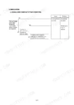
| Mechatronics System | 112-136 | Outline, Mode Selection System, Automatic Deceleration System, Power Boost System, Travel Speed Control System, Automatic Warming Up Function, Engine Overheat Prevention Function |
| Maintenance Standard | 187-224 | Operational Performance Test, Major Components, Track and Work Equipment |
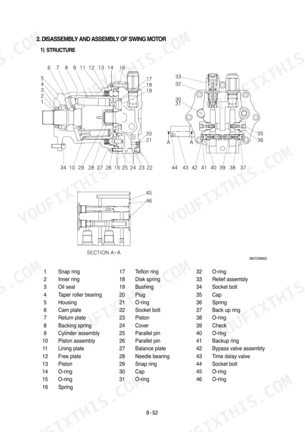
| Disassembly and Assembly | 225-277 | Precaution, Tightening Torque, Pump Device, Main Control Valve, Swing Device, Travel Device, Rcv Lever, Turning Joint |
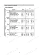
| Component Mounting Torque | 278-325 | Introduction Guide, Engine System, Electric System, Undercarriage, Structure, Work Equipment, Safety Hints |
| Pump Device | 326-347 | Main Pump Structure, Regulator Structure, Flow Control Function, Overload Preventive Function, Qmax Cut Control |
| Swing Device | 348-365 | Swing Motor Structure, Rotary Group, Make Up Valve, Relief Valve, Negative Brake |
| Travel Device | 366-381 | Travel Motor Structure, Counterbalance Valve, Negative Brake, Pressure Release Valve, Reduction Gear |
| Rcv Lever | 382-401 | Rcv Lever Structure, Pilot Valve Operation, Neutral Position, Tilted Handle Operation |
| Rcv Pedal | 402-407 | Rcv Pedal Structure, Pilot Valve Operation, Neutral Position, Tilted Pedal Operation |
| Main Control Valve | 408-465 | Main Control Valve Structure, Relief Valve Assembly, Boom Load Holding Valve, Center Bypass Valve, Load Check Assembly |
| Travel Device (Continued) | 466-513 | Travel Device Removal and Installation, Travel Motor Structure, Reduction Gear Disassembly, Travel Motor Disassembly |
| Work Equipment | 514-586 | Bucket Cylinder Removal, Arm Cylinder Removal, Boom Cylinder Removal, Bucket Assembly, Arm Assembly, Boom Assembly |
Quick Reference Specifications
| Specification | Value | Page |
|---|---|---|
| Bypass relief valve opening pressure | 1.5kgf/cm2 (21psi) | p. 34 |
| Bypass check valve setting pressure | 1.5kgf/cm2 (21psi) | p. 34 |
| Battery | 12V × 160Ah | p. 84 |
| Starter | Delco Remy 28MT 24V | p. 89 |
| Voltage | 20 ~ 32V | p. 163 |
| Resistance between CD-1 (1,2) | 130 ~ 150 ohm | p. 167 |
| Resistance between CN-51 (31,34) | 0 ~ 1 ohm | p. 167 |
| Clearance between shaft and bushing (Track roller) | 0.409 to 0.509 mm | p. 219 |
| Side clearance of roller (Track roller) | 0.12 to 1.18 mm | p. 219 |
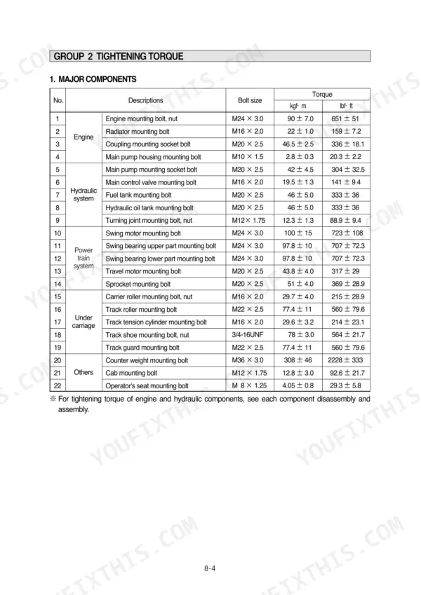
| Main pump housing mounting bolt | 2.8 ± 0.3 kgf·m | p. 230 |
| Main pump mounting socket bolt | 42 ± 4.5 kgf·m | p. 230 |
| Track shoe mounting bolt, nut | 78 ± 3.0 kgf·m | p. 230 |
Hyundai R360LC-7 Common Problems This Manual Covers
Hyundai R360LC-7 hydraulic functions sluggish, bucket and arm weak under load, slow cycle times
Check hydraulic oil level first; the tank holds 230 liters when full, per page 325. Test main relief pressure against the 330 kgf/cm2 spec on page 322. If oil is dark or milky, drain the tank and replace hydraulic filters; a plugged element opens the bypass relief at 1.5 kgf/cm2 (21 psi) and routes unfiltered oil through the pumps.
Manual Section: Hydraulic and Mechanical System Troubleshooting p. 141Engine cranks slowly or will not turn over at all on cold mornings
Load test the batteries; this machine runs two 12V, 160Ah units in series, per page 84. Measure system voltage at the starter, which should hold 20 to 32V per the chart on page 163. Clean and tighten battery grounds at the frame. If voltage checks good and cranking stays slow, pull the Delco Remy 24V starter and bench test it.
Manual Section: Electrical System Troubleshooting p. 163Machine pulls to one side traveling, tracks loose, rollers and idlers wearing unevenly
Measure track roller shaft-to-bushing clearance; replace rollers worn past the 0.409 to 0.509 mm limit on page 219. Check idler bushing clearance against the 0.35 to 0.435 mm spec on page 221. Retorque loose track shoe bolts to 78 kgf·m, the spec on page 229, and adjust track sag equally on both sides before road testing.
Manual Section: Maintenance Standard p. 219Coolant temperature climbs into the red zone during heavy digging or long travel runs
Check coolant level cold and inspect the radiator core for packed dirt; blow it out with compressed air from the fan side. Verify engine oil level too, since low oil runs hot; the sump takes 26.5 liters, per page 321. Inspect the fan belt for glazing and confirm the thermostat opens before condemning the water pump.
Manual Section: Electrical System Troubleshooting p. 223Engine stalls when hydraulic load comes on, idles rough, restarts hard when hot
Pull error codes from the cluster first; the code table on page 125 covers codes 1 through 58. Replace both fuel filters and bleed the system, checking for air leaks at the suction fittings. Test voltage while cranking; anything below the 20 to 32V range on page 163 starves the controllers and drops the engine under load.
Manual Section: Mechatronics System Troubleshooting p. 125Frequently Asked Questions
How do I clear the error codes on the Hyundai R360LC-7?
To delete all recorded error codes, select the recorded error (TIME Er) display mode on the cluster. Press the engine and select switches simultaneously for 2 seconds or more. The display will change to 'TIME Er : 00', indicating that all recorded error codes have been deleted from the CPU controller memory. p. 124
What are the torque specifications for the main pump mounting bolts on the R360LC-7?
The tightening torque for the main pump mounting socket bolts (M20 x 2.5) is 42 ± 4.5 kgf·m (304 ± 32.5 lbf·ft). p. 229
What is the tightening torque for the bucket cylinder head pin bolts?
The tightening torque for the M20 x 2.5 bolts used on the bucket cylinder head pin is 57.9 ± 8.7 kgf·m (419 ± 62.9 lbf·ft). p. 292
What is the capacity of the hydraulic oil tank for the R360LC-7?
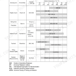
The hydraulic oil tank capacity is 230 liters (61 U.S. gal). p. 325
What is the standard engine oil quantity for the R360LC-7?
The engine oil quantity for the engine oil pan is 26.5 liters (7.0 U.S. gal). p. 325
How will I receive this Hyundai R360LC-7 Shop Manual?
Instant PDF download. You get the full 586-page searchable Shop Manual immediately after payment. Open it on your laptop, tablet, or phone right in the shop.
Is this Hyundai R360LC-7 Shop Manual printable?
Yes. Print a chapter or just the pages for the job at hand, for use in your own shop. Any home or office printer works.








Reviews
There are no reviews yet.