
Part of the Hyundai Repair Manuals.
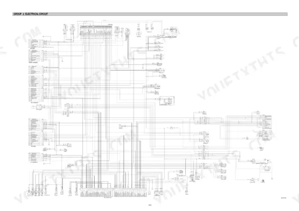
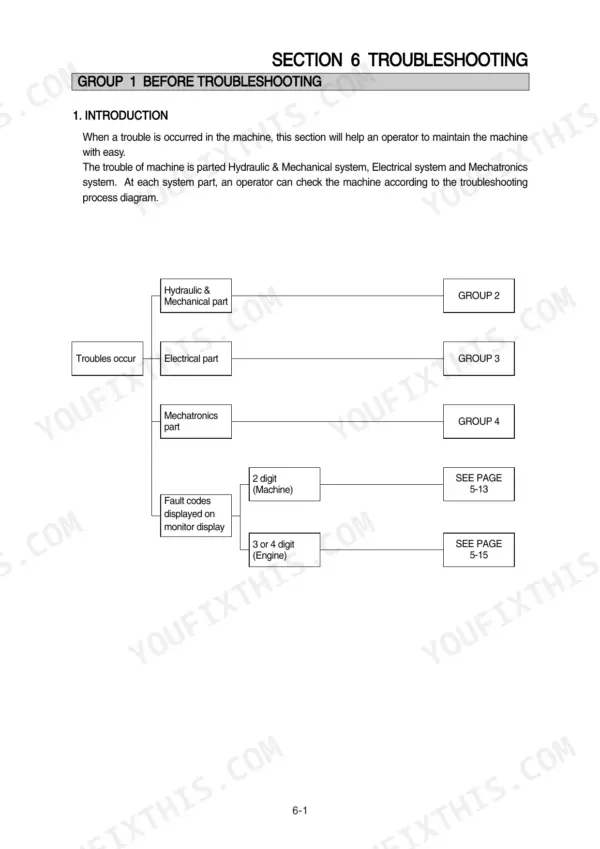
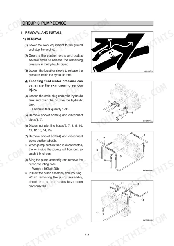
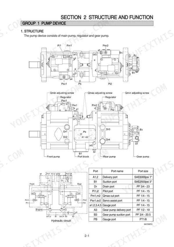
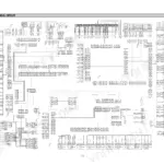
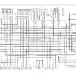
Need the factory answers for your Hyundai R360LC-7A? This 563-page Hyundai R360LC-7A service manual PDF covers the hydraulic excavator from pump device to turning joint, straight from the factory. You get full hydraulic circuit schematics with pilot and main circuit routing, electrical wiring diagrams with connector pinouts and component locations, and a troubleshooting section that walks hydraulic, electrical, and mechatronics faults step by step. Disassembly and assembly procedures cover the pump, main control valve, swing device, travel motors, RCV lever, and every cylinder on the boom, arm, and bucket. Set the pilot relief valve at 35 kgf/cm², and change the hydraulic filter once drain pressure passes 1.5 kgf/cm². No more chasing wiring faults with a multimeter and a prayer. Bookmarked and keyword-searchable; jump straight to the spec, then get back to work.
What's Inside This Hyundai R360LC-7A Manual
| System | Pages | Key Topics |
|---|---|---|
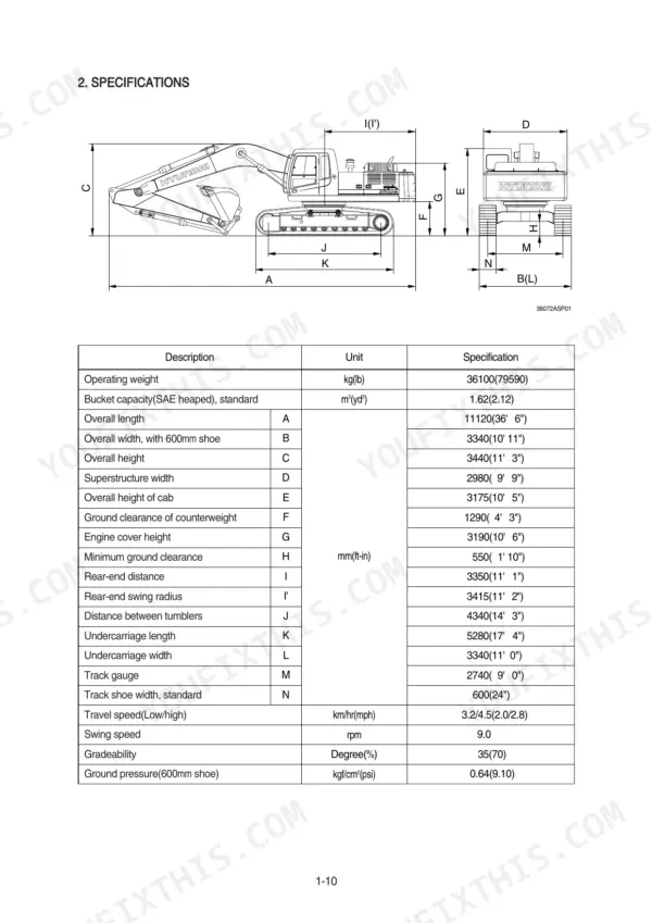
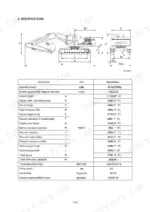
| General | 3-32 | Safety Hints, Specifications |
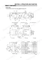
| Structure and Function | 33-145 | Pump Device, Main Control Valve, Swing Device, Travel Device, Rcv Lever, Rcv Pedal |
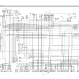
| Hydraulic System | 146-177 | Hydraulic Circuit, Main Circuit, Pilot Circuit |
| Electrical System | 178-226 | Component Location, Electrical Circuit, Electrical Component Specification |
| Mechatronics System | 227-282 | Outline, Mode Selection System, Monitoring System |
| Maintenance Standard | 333-371 | Operational Performance Test, Major Components, Track and Work Equipment |
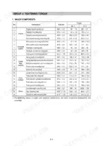
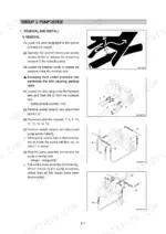
| Disassembly and Assembly | 372-548 | Precaution, Tightening Torque, Pump Device, Main Control Valve, Swing Device, Travel Device, Rcv Lever, Turning Joint |
| Component Mounting Torque | 549-563 | Introduction Guide, Engine System, Electric System, Undercarriage, Structure, Work Equipment |
Quick Reference Specifications
| Specification | Value | Page |
|---|---|---|
| Pilot relief valve setting pressure | 35kgf/cm2 | p. 151 |
| Bypass relief valve opening pressure | 1.5kgf/cm2 | p. 149 |
| Drain oil pressure limit | 1.5kgf/cm2 | p. 150 |
| Pressure switch (Travel, working) contact | 0.1 Ω | p. 199 |
| Air cleaner pressure switch contact (Low level) | 0 Ω | p. 202 |
| Play between piston(1) & shoe caulking section(3) | 0-0.1mm | p. 354 |
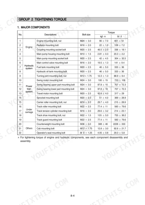
| Main pump mounting socket bolt torque | 42 ± 4.5 kgf·m | p. 555 |
| Main pump housing mounting bolt torque | 2.81 ± 0.3 kgf·m | p. 555 |
| Hexagon socket head bolt (M8) torque | 3.0 kgf·m | p. 377 |
| Hexagon socket head bolt (M10) torque | 5.8 kgf·m | p. 556 |
| Tightening torque for socket bolts | 25 kgf·m (181 lbf·ft) | p. 408 |
| Tightening torque for relief sleeve | 10 kgf·m (72.3 lbf·ft) | p. 410 |
Hyundai R360LC-7A Common Problems This Manual Covers
Hyundai R360LC-7A all hydraulic functions weak and slow, working pressure low across boom, bucket, and travel
Check pilot pressure first; the pilot relief valve must hold 35 kgf/cm2, the spec listed on page 151. If pilot supply is good, test main relief operation using the diagnostic steps beginning. Replace a suspect main relief cartridge and torque it to 12.2 to 14.3 kgf·m (88.2 to 103 lbf·ft) as shown on page 439.
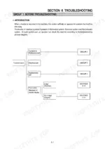
Manual Section: Hydraulic and Mechanical System TroubleshootingBoom drifts down and arm creeps toward the no-load side with pilot levers in neutral
Test each port relief valve on the affected circuit; a valve opening below its set pressure lets the cylinder bleed down. Swap suspect port relief valves between circuits to confirm the fault follows the valve. Install the replacement with a 36 mm wrench and torque it to 12.2 to 14.3 kgf·m per page 439.
Manual Section: Disassembly and Assembly p. 439Hydraulic oil overheats after an hour of digging, all functions fade once the system is hot
Drain and refill with clean oil if a sample shows contamination, then replace the return filter; a clogged element pushes dirty oil past the bypass relief valve, which opens at 1.5 kgf/cm2 as noted on page 149. Verify drain line pressure stays within the 1.5 kgf/cm2 limit on page 150, then recheck oil temperature under load.
Manual Section: Hydraulic System p. 149Main pump grinding noise at operating temperature, flow drops off under full load
Inspect the suction line for air leaks and collapse before condemning the pump. Disassemble the pump and measure play between each piston and its shoe caulking section; the standard is 0 to 0.1 mm per page 354. Replace worn rotating groups, then remount the pump and torque the mounting socket bolts to 42 ± 4.5 kgf·m, listed on page 555.
Manual Section: Maintenance Standard p. 354Power mode cuts out under load, pump pressure readings on the cluster jump around erratically
Test each pump pressure transducer with the key on: output should read 1V at 0 bar and rise to 5V at 500 bar for pumps 1 and 2, per page 206. Check connector pins for corrosion and trace harness faults using the wiring diagram on page 182. Replace any transducer reading outside those values.
Manual Section: Electrical System p. 206Frequently Asked Questions
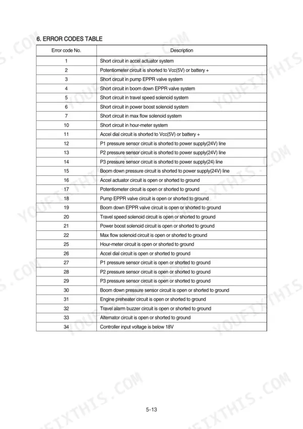
How do I clear error codes on a Hyundai R360LC-7A excavator?
To delete all recorded error codes, select the recorded error (TIME Er) display on the cluster. Press the engine switch and the select switch at the same time for 2 seconds or more. The cluster display will change to 'TIME Er : 00', indicating that the CPU controller has deleted all recorded error codes from the memory. p. 239
What is the procedure to check the hydraulic pump pressure on a Hyundai R360LC-7A?
To check the main pump delivery pressure, stop the engine and remove the top cover of the hydraulic tank oil supply port. Install a connector and pressure gauge assembly to the main pump gauge ports (a1, a2). Start the engine, set the mode selector to M mode, and measure the delivery pressure in high idle. p. 352
What are the replacement specifications for the Main relief valve?
The main relief valve should be replaced if it is damaged or if the spring is abnormal. When inspecting, ensure the contacting face of the valve seat and poppet are free of defects. The replacement of O-rings and back-up rings is required in principle. p. 356
What is the tightening torque for the engine mounting bolts on the R360LC-7A?
The engine mounting bolts and nuts (M24 x 3.0) should be tightened to a torque of 90 ± 7.0 kgf·m (651 ± 51 lbf·ft). p. 376
What is the standard clearance between the piston and cylinder bore for the main pump?
The standard clearance between the piston and cylinder bore (D-d) is 0.038mm, with a recommended replacement value of 0.078mm. If the clearance exceeds this, the piston or cylinder should be replaced. p. 354
How is this Hyundai R360LC-7A Service Manual delivered?
All 563 pages arrive as one searchable PDF at checkout. Read it at the desk, then take the phone out to the machine.
Can I print pages of this Hyundai R360LC-7A manual for my own shop?
Yes. Print the sections you need to take out to the shop for your own use. Standard letter or A4 paper works.






Reviews
There are no reviews yet.