

Part of the JCB Repair Manuals.
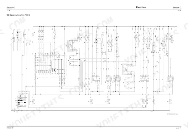
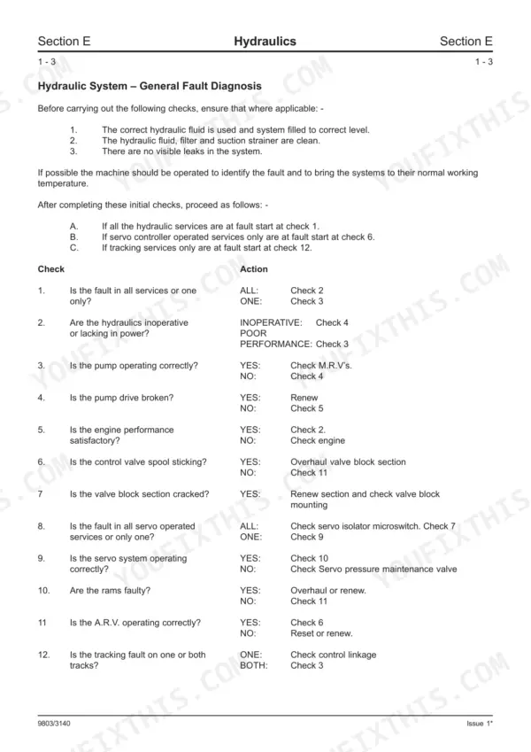
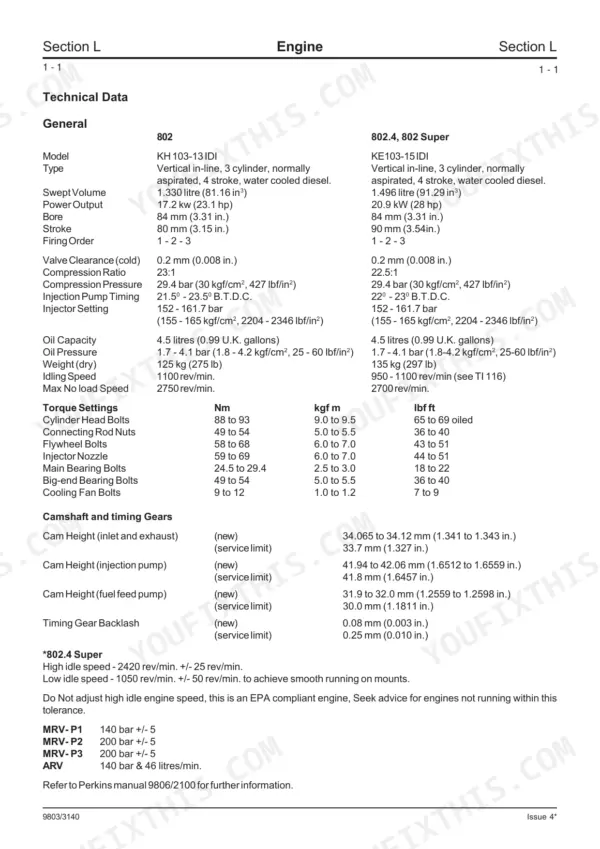
Need to fix the JCB 802, 802.4, Super, or 801.4 mini excavator sitting in your bay? All 293 pages of this JCB 802 service manual PDF (OEM #9803/3140 Issue 4) focus on getting your machine back to factory condition. You get complete hydraulic circuit schematics, detailed wiring diagrams, and a full section of step-by-step pump teardown procedures. Open the file to find exact flow testing methods, track gearbox dismantling instructions, and fault-finding charts to track down stubborn leaks. Lock down the cylinder head bolts to exactly 88-93 Nm, and tighten the track motor valve bolts to 51-64 Nm before testing the system. Don't risk a costly comeback by guessing on pressures. Download the bookmarked file, pull it up on your shop tablet, and get to work.
What's Inside This JCB 802, 802.4, 802 Super, 801.4 Manual
| System | Pages | Key Topics |
|---|---|---|
| General Information | 1-48 | Contents, Identifying Your Machine, Storage, ROPS, Tops and Fogs, Introduction, Entering/Exiting the Cab, Cab, Opening the Windscreen |
| Care & Safety | 49-54 | Contents, Safety Notices, General Safety, Operating Safety, Maintenance Safety |
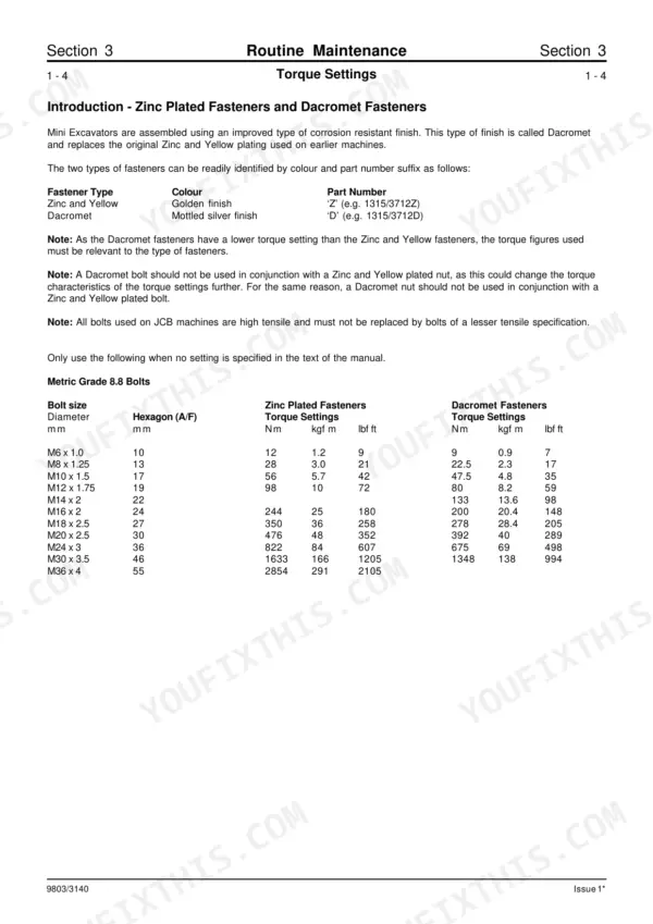
| Routine Maintenance | 55-83 | Lubricants and Capacities, Engine Lubrication Chart, Lubricants - Health and Safety, Torque Settings, Hydraulic Fittings and Torque Settings, Service Schedule, Greasing |
| Attachments | 84-105 | Available Attachments, Buckets (Selection, Removal, Installing a Bucket, Replacing Bucket Teeth), Quickhitch, Hydraulic Attachment Circuits |
| Body & Framework | 106-119 | Bucket Ram Pivot and Linkage (Removal, Inspection and Replacement), Dipper (Removal and Replacement), Boom (Removal, Kingpost (Removal and Replacement) |
| Electrics | 120-150 | Technical Data, Battery, Alternator (Removal & Replacement), Starter Motor (Removal & Replacement), Beacon (Mounting, Bulb Change), Schematic Diagrams |
| Controls | 151-159 | Excavator and Dozer Levers (Removal & Replacement), Servo Hand Controllers - 802 (Removal & Replacement) |
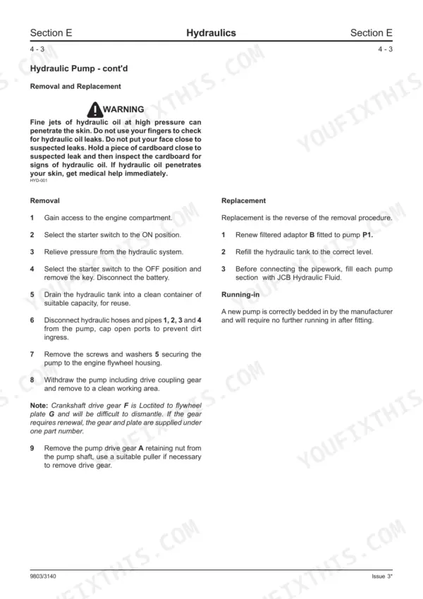
| Hydraulics | 160-227 | Technical Data, Hydraulic Circuit (Circuit Description), Servo Circuit (Circuit Description), Hydraulic Pump (Operation, Removal, Dismantling & Assembly, Flow Testing) |
| Gearboxes | 228-240 | Technical Data, Track Gearbox (Operation, Removal and Replacement, Dismantling & Assembly) |
| Track & Running Gear | 241-252 | Tracks (Clean, Inspect, Removal & Replacement, Steel Track, Rubber Track), Track Rollers (Removal & Replacement, Dismantling & Assembly, Metallic Face Seals) |
| Engine | 253-293 | Technical Data, Oil Pressure Relief Valve (Removal & Replacement), Oil Sump, Suction Pipe & Strainer (Removal & Replacement) |
Quick Reference Specifications
| Specification | Value | Page |
|---|---|---|
| Cylinder Head Bolts (oiled) | 88-93 Nm (9.0-9.5 kgf m, 65-69 lbf ft) | p. 60 |
| Track Motor Valve Bolts (Item 1) | 51-64 Nm (5.2-6.6 kgf m, 38-47 lbf ft) | p. 186 |
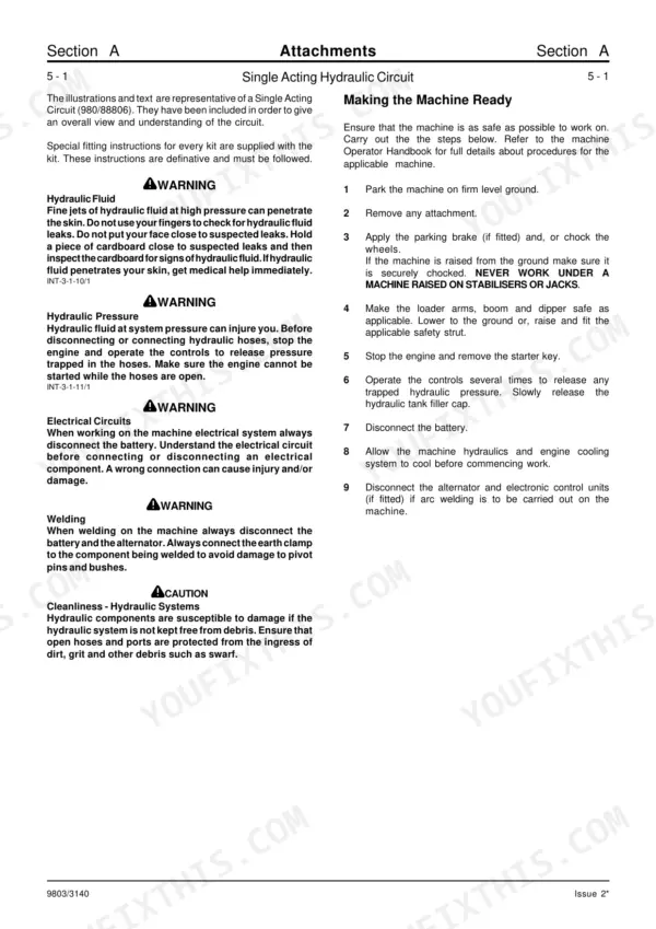
| Hydraulic System Pressure Release (venting) | Operate the controls several times to release any trapped hydraulic pressure. Slowly release the hydraulic tank filler cap. | p. 91 |
| General Hydraulic Leak Check | Check for visible leaks in the system. If hydraulic fluid penetrates skin, get medical help immediately. | p. 163 |
| Track Motor Oil Leakage (between valve and motor) | Tighten bolts, or replace O-rings and gasket. | p. 192 |
| Engine Oil Filter Replacement Interval | First 100 Hours Only, then Every 250 Operating Hours (Or Monthly) | p. 63 |
| Engine Oil Filter Tightening | hand tight and then one quarter turn | p. 76 |
| Fuel Filter Element Replacement Interval | Every 500 Operating Hours (Or 6 Months) | p. 63 |
| Fuel Sediment Bowl Drain Interval | Every 50 Operating Hours (Or Weekly) | p. 63 |
| Fan Belt Adjustment Interval | Every 50 Operating Hours (Or Weekly) | p. 63 |
| Fan Belt Tension (slack) | 5 mm (0.2 in.) | p. 72 |
| Track Gearbox Oil Capacity (each) | 1.2 litres (0.26 UK gal) | p. 56 |