
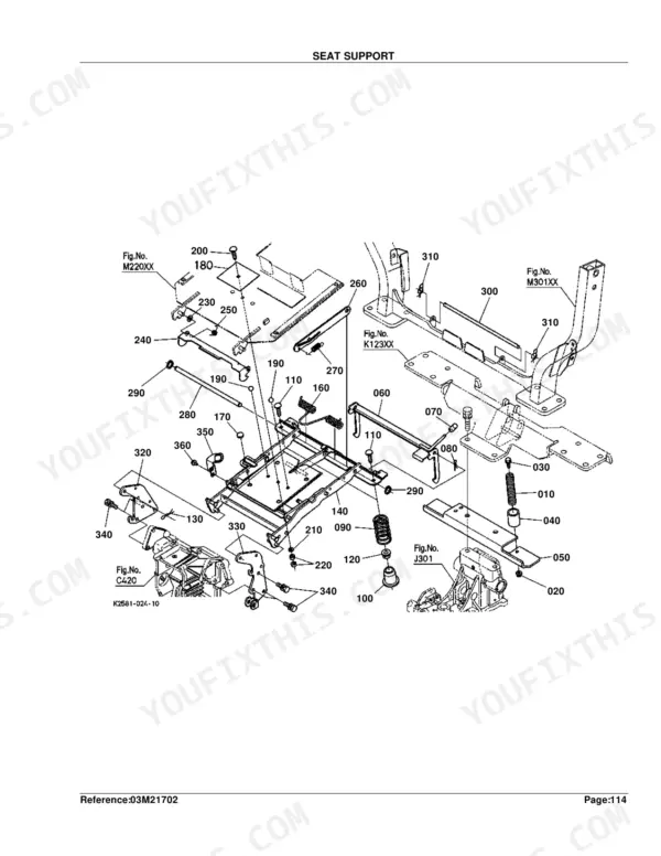
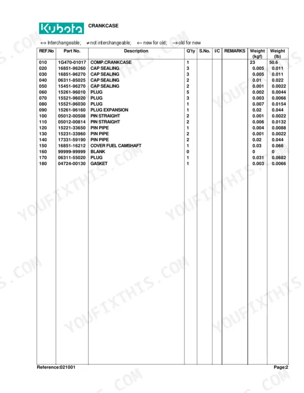
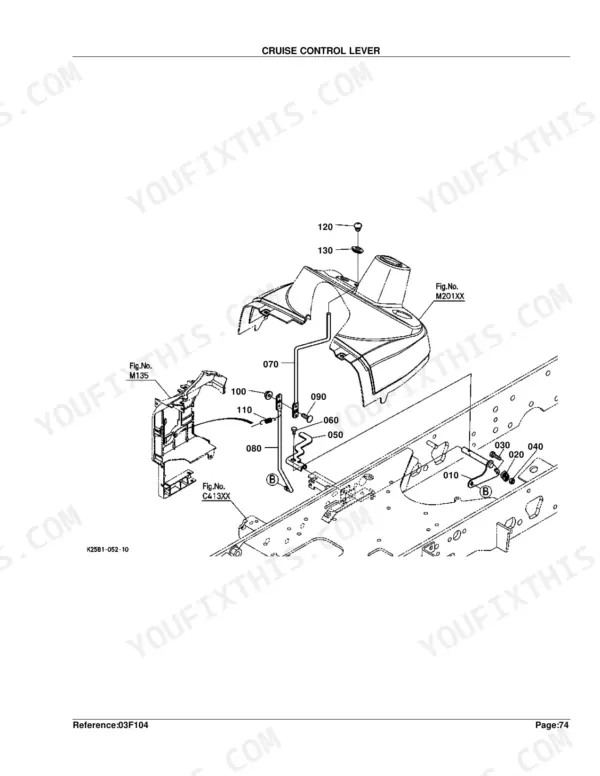
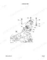
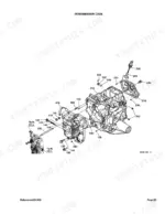
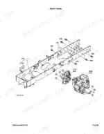
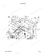
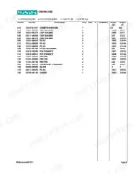
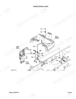
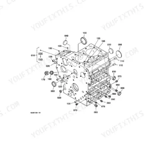
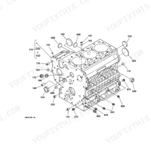
Part of the Kubota Parts Manuals.
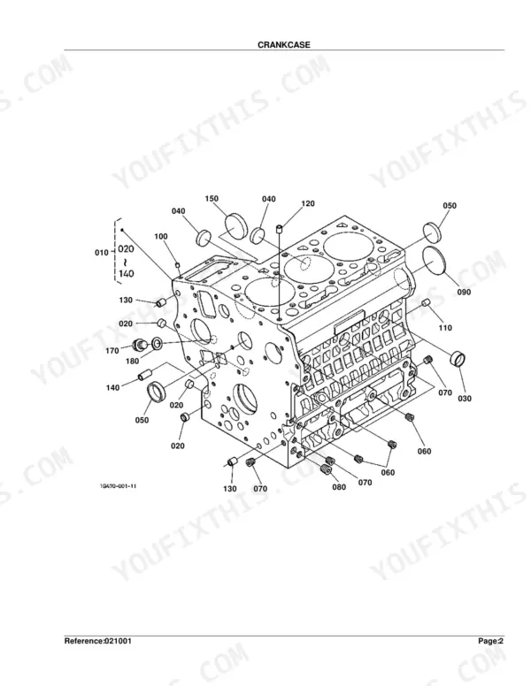
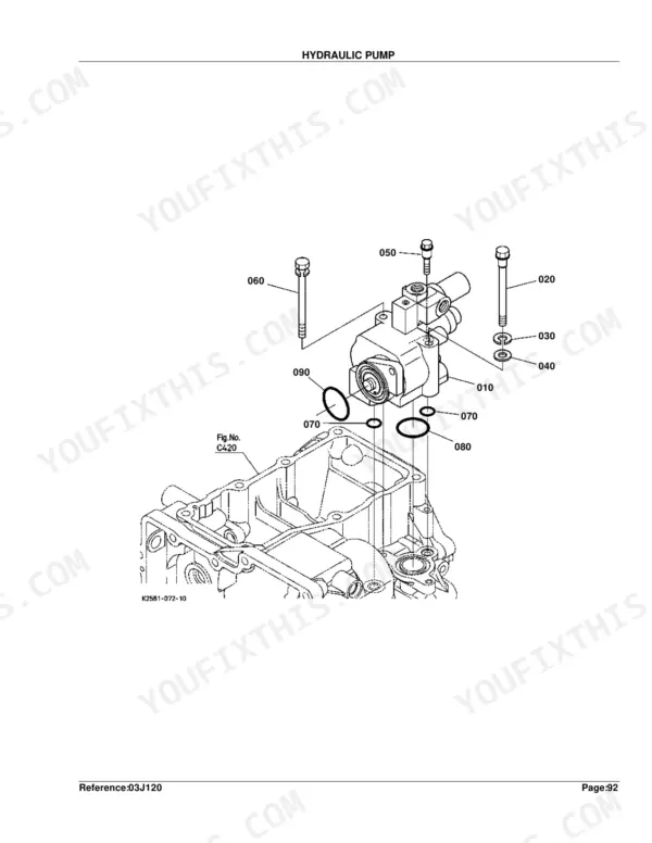
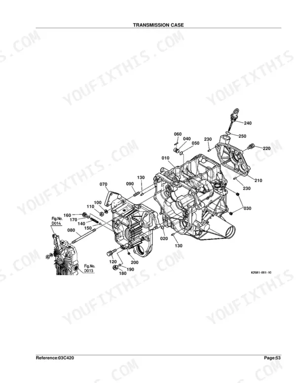
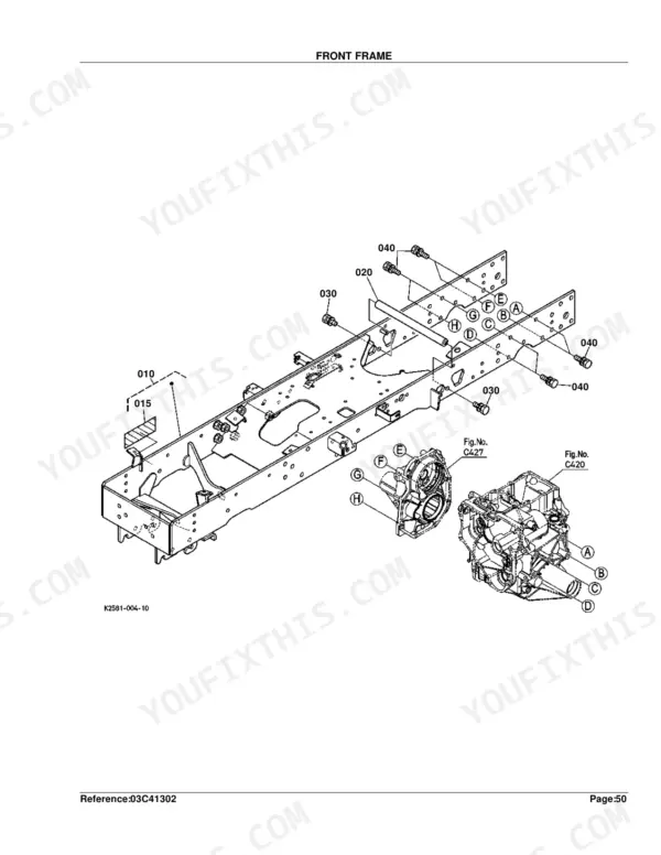
This is the Kubota illustrated parts catalog for the BX24D compact tractor (publication reference 11090). Every assembly is drawn as an exploded diagram beside a numbered parts list, so you can identify the exact component and its Kubota part number before ordering.
Coverage spans the whole machine: engine from crankcase to crankshaft, the fuel and injection system, cooling, the alternator and starter, the four-part HST and transmission, front and rear axles, brakes, steering, hydraulics, and the electrical panel, lights, and wiring.
Use it to match part numbers to your serial number, separate interchangeable parts from superseded ones, and put together an accurate order for engine, driveline, hydraulic, or electrical work on this 2004 to 2009 tractor.
What's Inside This Kubota BX24D Parts Manual
| System | Pages | Key Topics |
|---|---|---|
| Clutch & Transmission | Transmission Case, Clutch Shaft/Output Shaft, Range Gear Shaft, Range Gear Shift Fork, PTO Gear Shift Fork, PTO Gear Shift Arm, Differential Lock Shift Fork, Range Gear Shift Lever, PTO Gear Shift Lever | |
| Fuel System | Fuel Camshaft and Governor Shaft, Idle Apparatus, Stop Solenoid, Injection Pump, Governor, Speed Control Plate, Nozzle Holder and Glow Plug, Nozzle Holder, Air Cleaner, Accelerator Lever, Fuel Tank, Fuel Pipe, Speed Control Pedal | |
| Cooling System | Water Flange and Thermostat, Water Pump, Fan, Water Pipe, Radiator | |
| Engine | Crankcase, Oil Pan, Cylinder Head, Gear Case, Head Cover, Oil Filter, Dipstick and Guide, Oil Pump, Main Bearing Case, Camshaft and Idle Gear Shaft, Piston and Crankshaft, Flywheel, Valve and Rocker Arm, Inlet Manifold, Exhaust Manifold, Muffler | |
| Electrical System | Alternator and Pulley, Alternator, Starter, Oil Switch/Thermometer, Battery, Panel Board, Switch/Sensor, Head Light, Hazard Light/Tail Light, Electrical Wiring | |
| Undercarriage & Travel | Steering Controller | |
| PTO | PTO Shaft, Mid PTO, PTO Select Lever, PTO Protector | |
| Rear Axle, Differential & Brakes | Rear Axle Case, Rear Differential, Rear Axle, Brake, Brake Pedal, Differential Lock Pedal, Differential Gear Shaft, Front Axle Case, Rear Wheel | |
| Front Axle & Steering | Propeller Shaft, FWD Idle Shaft, Front Wheel Propeller Shaft, Front Wheel Drive Lever, Front Differential Case, Front Differential, Front Axle, Steering Handle, Steering Linkage, Steering Cylinder, Front Wheel | |
| Hydraulics & 3-Point Hitch | Hydraulic Control Lever, Hydraulic Pump, Hydraulic Oil Line, Hydraulic Cylinder, Control Valve, Top Link, Lower Link, Lift Rod, Top Link Bracket, Front Control Valve Kit | |
| Body & Operator Station | Front Frame, Sub Frame, Front Guard, Bonnet, Bonnet Side, Panel Frame, Fender, Seat Support, Seat, Step, ROPS, Smv Emblem | |
| Decals & Accessories | Label, Accessories and Service Parts | |
| Other Components | Gp Idle Shaft, Cruise Control Lever, Mower Rear Link RH, Mower Rear Link LH, Front Glille Support, Center Pillar, Manual Holder |
Quick Reference Specifications
| Specification | Value | Page |
|---|---|---|
| FUSE amperage | 10A | p. 103 |
| Injection Pump Shim Thickness | 0.20mm | p. 38 |
| Nozzle Holder Washer Adjusting Thickness | 0.900mm | p. 46 |
| Battery Type | 26RA | p. 93 |
| Head Light Bulb Wattage | 37.5W | p. 99 |
| Electrical Wiring Fuse Rating | 10A | p. 103 |
| Clutch Gear Boss Tooth Count | 20T | p. 115 |
| HST 2 Shim Thickness | 0.5mm | p. 121 |
| Rear Differential Shim Thickness | 0.6mm | p. 133 |
| Front Wheel Tire Size | 18*8.5-10 | p. 245 |
| Rear Wheel Tire Size | 26*12.00-12 | p. 251 |
Kubota BX24D Common Problems This Manual Covers
Bogs down or loses power under load
Owners report the BX24D bogging or stalling under mower and PTO load when the air intake is restricted. The air cleaner diagram identifies the element and housing parts to service the intake.
Manual Section: Air Cleaner p. 72Panel board acts up after moisture
The instrument panel board is prone to moisture intrusion, causing erratic gauges and warning behavior. The panel board diagram lists the board and its revised part number.
Manual Section: Panel Board p. 94Blown fuses or electrical faults
Intermittent electrical operation and repeat fuse blows send you to the wiring layout. The electrical wiring section shows fuse ratings and harness routing for the tractor.
Manual Section: Electrical Wiring p. 102Overheating during heavy use
A tired water pump, thermostat, or gaskets let these tractors run hot under sustained load. The water pump exploded view identifies the pump and sealing parts for a cooling-system reseal.
Manual Section: Water Pump p. 62Hard starting or fuel delivery loss
Rough running and stalling often trace to the injection pump and fuel delivery. The injection pump diagram breaks the pump down for parts identification.
Manual Section: Injection Pump p. 37HST will not drive after service
Loss of drive in the hydrostatic transmission points to the multi-part HST unit. The HST 1 exploded view begins the breakdown of the assembly and its components.
Manual Section: HST 1 p. 118Frequently Asked Questions
What does this catalog cover?
It covers the complete Kubota BX24D: engine, fuel and injection, cooling, electrical, the four-section HST and transmission, front and rear axles, brakes, steering, and hydraulics. Each system is an exploded diagram with a matching numbered parts list.
Is this a repair manual or a parts catalog?
It is a parts catalog. It provides exploded diagrams, part numbers, quantities, and serial-number interchange notes for identifying and ordering parts. It does not include repair steps or torque specifications.
What fuse ratings does the BX24D use?
The electrical wiring section lists 10A, 15A, 20A, and 50A fuses. Match the rating shown in the diagram to protect the circuit and avoid repeat failures. p. 102
What battery does the BX24D take?
The battery section specifies a 26RA type battery. The exploded view shows the battery, hold-down, and cable parts so you can order a correct replacement and mounting hardware. p. 92
What do I get after purchasing this Kubota BX24D manual?
A 281-page Parts Catalog in searchable PDF, ready the moment your checkout completes. Open it on a computer, tablet, or phone with no shipping wait.
Can I print pages of this manual for my own shop?
Yes. Print the pages or sections you need for your own shop use. Any standard printer works.


Reviews
There are no reviews yet.