

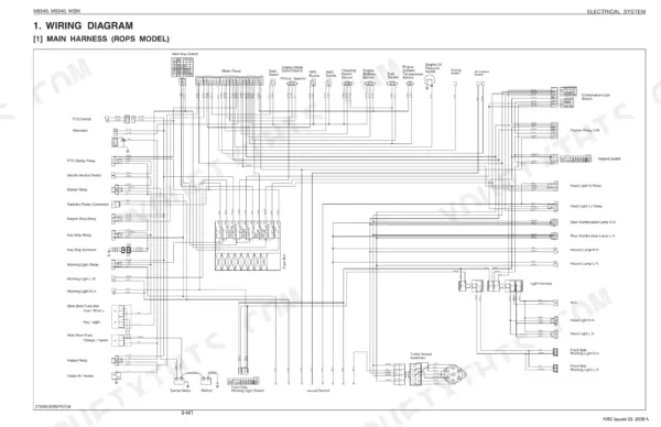
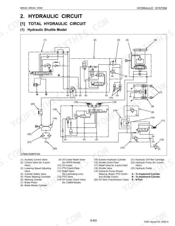
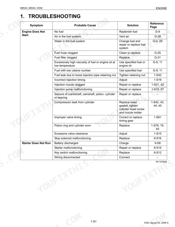
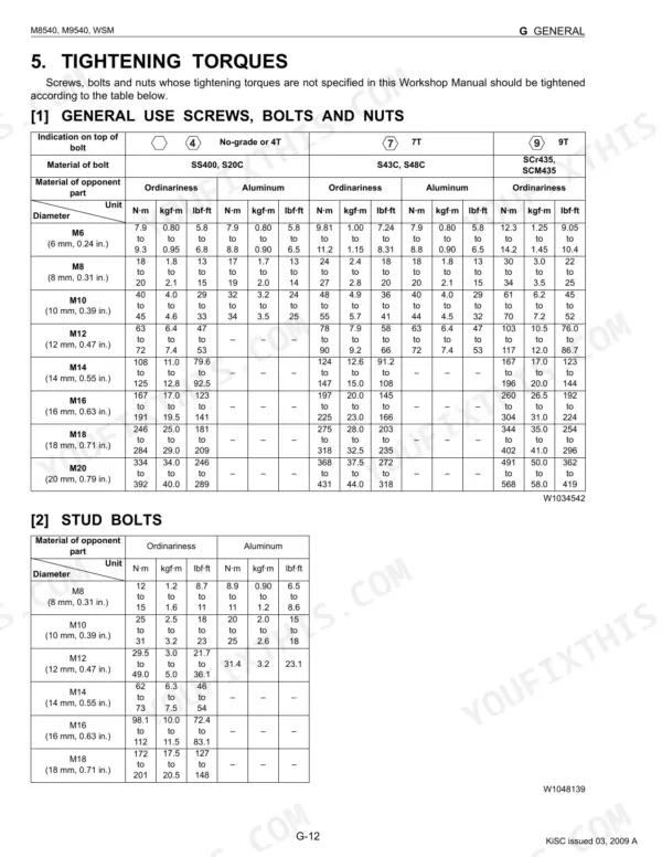


This Kubota Workshop Manual covers the M8540 and M9540 tractors built between 2006 and 2009, powered by the V3800DI-TE2 and V3800DI-TE3 diesel. It runs 662 searchable pages and is the factory service document for both ROPS and cabin versions.
The manual is split into General, Mechanism, and Servicing, then organized by system: Engine, Clutch, Transmission, Rear Axle, Brakes, Front Axle, Steering, Hydraulic System, Electrical System, and Cabin. Each servicing chapter carries troubleshooting, factory specifications, tightening torques, and checking and adjusting procedures.
With it you can rebuild the clutch and transmission, service the hydraulics and 3-point lift, bleed and adjust the brakes, trace wiring faults, and set the engine to Kubota tolerances. It is written for owners and independent mechanics maintaining or restoring these mid-size Kubota tractors.
What's Inside This Manual
| System | Pages | Key Topics |
|---|---|---|
| G General | 21-106 | General |
| Engine | 107-211 | Cylinder Head and Valves, Fuel System, Lubricating System, Cooling System, Piston and Connecting Rod, Turbocharger |
| Clutch | 212-270 | Clutch Pedal Free Travel, Traveling Clutch, PTO Clutch, Damper Disc, Release Holder and Lever |
| Transmission | 271-370 | Shuttle Lever, Main Gear Shifting, Shuttle Valve, Shift Fork and Synchronizer, PTO Gear Section, Differential Gear |
| Rear Axle | 371-390 | Planetary Gear, Brake Section, Rear Axle Assembly, Bearings |
| Brakes | 391-416 | Traveling Brake, Parking Brake, Master Cylinder Assembly, Bleeding Brake System |
| Front Axle | 417-449 | Bevel Gear Case, Differential Gear, Knuckle Shaft, Bearings |
| Steering | 450-470 | Steering Controller, Steering Cylinder, Hydraulic Pump, Relief Valve Setting Pressure, Rod to Bushing |
| Hydraulic System | 471-522 | Hydraulic Pump, Relief and Safety Valve, Position and Draft Control Linkage, Hydraulic Cylinder, Oil Cooler Relief Valve, Lift Arm and Top Link Bracket |
| Electrical System | 523-596 | Wiring Diagram, Electrical Circuit Retailed Chart, Starting System, Instrument Panel, Opc (Operator Presence Control), Lighting System |
| Cabin | 597-662 | Structure, Compressor, Air Conditioner Unit, System Control, Air Flow, Air Control Vent |
Quick Reference Specifications
| Specification | Value | Page |
|---|---|---|
| All Models | ||
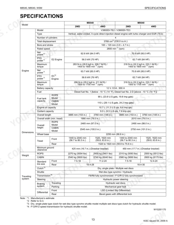
| Fuel tank capacity (ROPS Model) | 90 L (23.8 U.S.gals, 19.8 Imp.gals) | p. 15 |
| Fuel tank capacity (CABIN Model) | 110 L (29.1 U.S.gals, 24.2 Imp.gals) | p. 15 |
| Total displacement | 3769 cm3 (230.0 cu.in.) | p. 15 |
| Rated speed | 2600 min−1 (rpm) | p. 15 |
| Engine oil capacity | 10.7 L (11.3 U.S.qts, 9.4 Imp.qts) | p. 15 |
| Coolant capacity | 9.0 L (9.5 U.S.qts, 7.9 Imp.qts) | p. 15 |
| Hydraulic pump capacity | 64.3 L (17 U.S.gals, 14 Imp.gals) / min. | p. 16 |
| Hydraulic system pressure | 19.6 MPa (200 kgf/cm2, 2844.7 psi) | p. 16 |
| PTO speed | 540 min−1 (rpm) at 2205 min−1 (rpm) | p. 16 |
| Cylinder Head Surface Flatness (Allowable Limit) | 0.05 mm (0.0020 in.) | p. 132 |
| M8540 | ||
| Net power (E2 Engine), M8540 | 62.6 kW (84.0 HP) | p. 15 |
| M9540 | ||
| Net power (E2 Engine), M9540 | 70.8 kW (95.0 HP) | p. 15 |


