Part of the New Holland Repair Manuals.
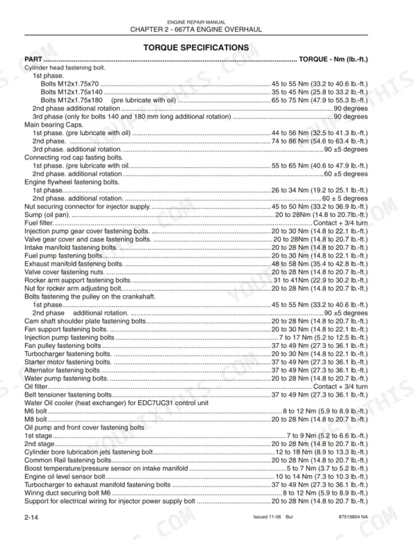
Bearing clearances and cylinder head torque phases for the 667TA series come from one place: New Holland's 150 page repair manual, OEM 87519804 NA, covering six engine variants. Common rail injection, EGR, lubrication and cooling each get a chapter in the 667TA series repair manual PDF, and the electrical section maps component locations and sensor cabling pinouts. A third of the book covers the bench overhaul: crankcase checks, crankshaft and flywheel, valve seats and guides, then ring installation and valve timing. Fuel holds at a constant 5 bars (72 psi) off the low pressure regulator valve, and your M12x1.75x70 head bolts come up to 45 to 55 Nm, then a further 90 degrees. Some rebuilds happen at night with no one left to call. Bookmarks land you on valve timing or the torque tables in seconds, and a search term pulls the spec you need before the head goes back on.
What's Inside This New Holland 667TA Series Repair Manual
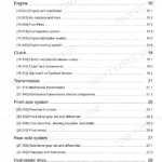
| System | Pages | Key Topics |
|---|---|---|
| Engine Repair Manual | 1 | |
| Revision History | 2 | Issue, Issue Date, Applicable Machine, Remarks |
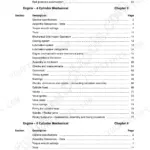
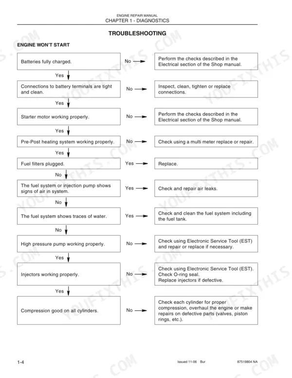
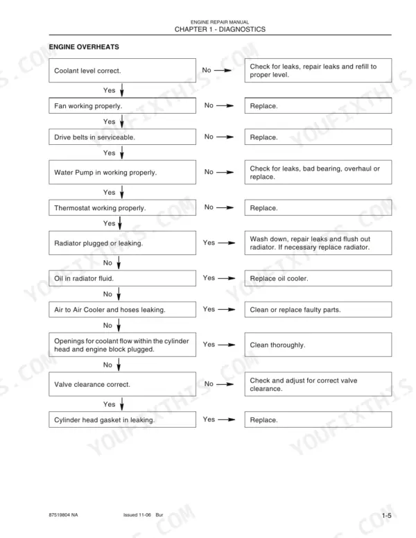
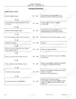
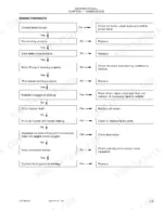
| Diagnostics | 5-16 | Table of Contents (Cnh- EST Diagnostic Tool, Troubleshooting) |
| 667TA Engine Overhaul Introduction and General Features | 17-29 | Engine Coding, Engine Properties, General Engine Features, Crank Gear Components, Cylinder Assembly |
| Engine Lubrication and Cooling Systems | 30-54 | Valve Gear, Engine Lubrication, Oil Cooler, Engine Cooling, Water Pump |
| High Pressure Electronic Injection System (Common Rail) | 55-72 | EDC7UC31 Control Unit, Fuel Supply System, Common Rail, Electro-Injector, Pressure Limiter |
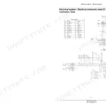
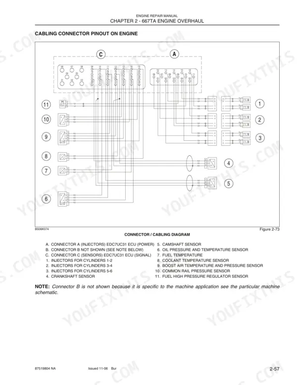
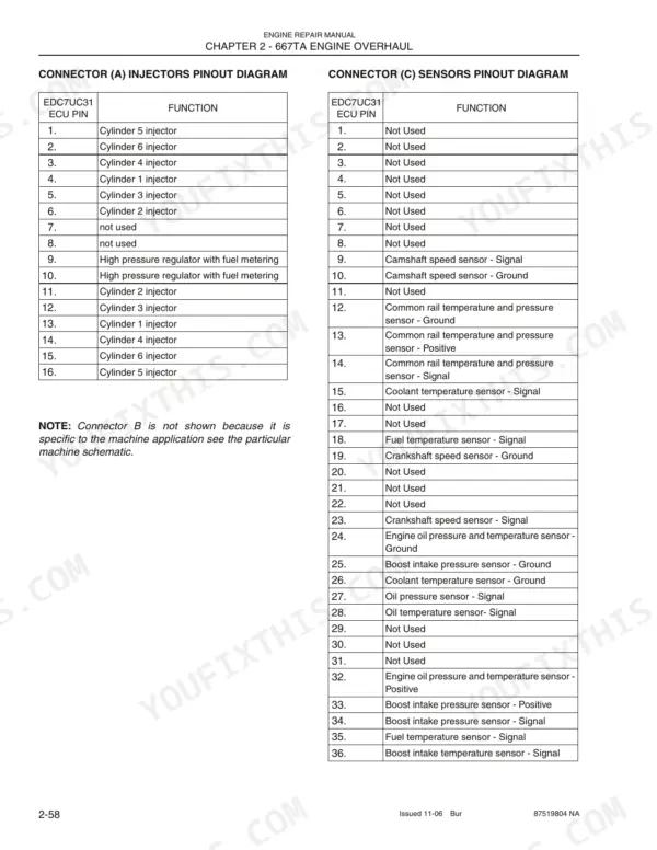
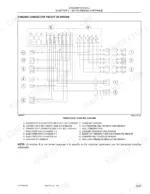
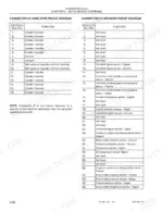
| Electrical Components and Diagnostics | 73-89 | Electrical Components Location, Cabling Pinout, Crankshaft Sensor, Camshaft Sensor, Fuel System Checks |
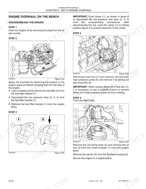
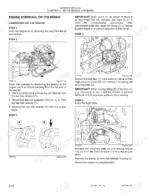
| Engine Disassembly and Overhaul Procedures | 90-114 | Disassembling the Engine, Crankcase Checks, Crankshaft, Connecting Rod-Piston Assembly, Flexing and Twisting Checks |
| Engine Reassembly and Final Adjustments | 115-140 | Installing Piston Rings, Installing Connecting Rod-Piston Assemblies, Valve Timing, Flywheel Cover Case, Engine Installation |
| Charging and Start-Up | 141-150 | Table of Contents (Starter Motor, Alternator) |
Quick Reference Specifications
| Specification | Value | Page |
|---|---|---|
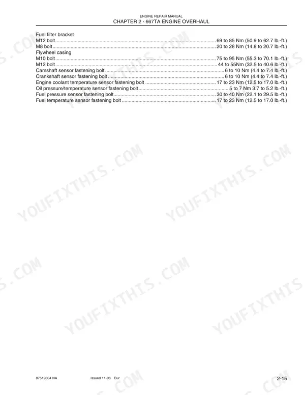
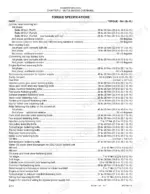
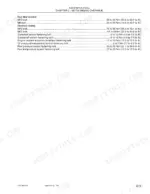
| Cylinder head fastening bolt | 1st phase: 45 to 55 Nm (33.2 to 40.6 lb.-ft.) for M12x1.75x70, 35 to 45 Nm (25.8 to 33.2 lb.-ft.) for M12x1.75x140, 65 to 75 Nm (47.9 to 55.3 lb.-ft.) for M12x1.75x180; 2nd phase: 90 degrees; 3rd phase: 90 degrees | p. 32 |
| Fuel filter tightening | 3/4 of a turn after the gasket makes contact | p. 140 |
| Nut securing connector for injector supply | 45 to 50 Nm (33.2 to 36.9 lb.-ft.) | p. 32 |
| Starter motor fastening bolts | 37 to 49 Nm (27.3 to 36.1 lb.-ft.) | p. 32 |
| Low pressure regulator valve pressure | 5 bars (72 psi.) | p. 59 |
| Common rail safety relief valve pressure | 1.3 to 2 bars (19 to 29 psi.) | p. 59 |
| Minimal operating pressure | 250 bar (3626 psi.) | p. 71 |
| Cylinder head fastening bolt tightening sequence | 1st phase: 30-40 Nm (12x1.75x130 mm) or 50-60 Nm (12x1.75x150 mm); 2nd phase: 90° ± 5°; 3rd phase: 90° ± 5° | p. 131 |
| Starter motor fastening nuts torque | 50 to 60 Nm (36.9 to 44.3 lb.-ft.) | p. 140 |
| Cylinder head fastening bolt 1st phase (M12x1.75x70) | 45 to 55 Nm | p. 32 |
| Cylinder head fastening bolt 1st phase (M12x1.75x140) | 35 to 45 Nm | p. 32 |
| Cylinder head fastening bolt 1st phase (M12x1.75x180) | 65 to 75 Nm | p. 32 |