
Part of the New Holland Repair Manuals.
This is New Holland BigBaler service manual part number 47969453, 1st edition February 2016. It covers the 230P, 230S, 330P, 330R, 330S, 340R and 340S from serial series 4137 and up.
This service manual gives New Holland's own figures for the main gearbox, slip clutch, hydraulic circuits, CAN/ISOBUS, fault codes, pickup, rotor, plunger, knotters and greasing. Crank bolt torque is 1700 N·m (1254 lb ft) on a 230 or 330, but only 1000 N·m (738 lb ft) on a 340.
What's Inside This New Holland BigBaler 230, BigBaler 330, BigBaler 340 Manual
| System | Pages | Key Topics |
|---|---|---|
| Introduction | 1-38 | Safety Rules, Standard Torque Data, Chain Wear Tables, Hydraulic Contamination, Product Identification |
| Power Take-Off (PTO) | 39-190 | PTO Drive Shaft, Exploded View, Constant Velocity Universal Joint, Troubleshooting, Guards, Overhaul, Flywheel, Special Tool for Central Lock Nut, Remove, Install, Main Gearbox, General Specification, Shimming, Input Shaft Torque, Sectional View, Disassemble, Assemble, Main Drive Slip Clutch, Static Description |
| Hydraulic Systems | 191-244 | Bale Density Circuit, Fault Finding, Hydraulic Schema, Hydraulic Control Valve, Hydraulic Cylinders, Knife Positioning Circuit, Hydraulic Cylinder, Bale Eject Circuit, Bale Eject and Bale Chute Hydraulic Schema, Partial Bale Eject, Hydraulic Symbol, Rear Bale Chute and Tandem Auto-Steer Lock, Orifice, Tandem Auto-Steer Lock Circuit Hydraulic Schema |
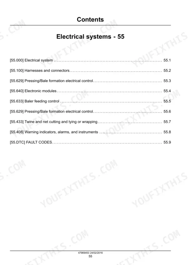
| Electrical System | 245-253 | Component Identification |
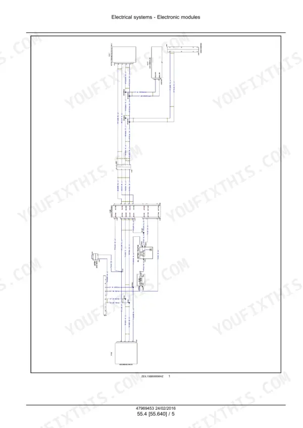
| Harnesses, Connectors and Electrical Schematics | 254-615 | Special Tools, Connectors, Electrical Schematic, Power Distribution, Moisture Control, Camera Kit |
| Pressing and Bale Formation Electrical Control | 616-625 | Plunger Load Sensor, Visual Inspection, Electrical Adjust |
| Electronic Modules and CAN Bus | 626-643 | Controller Area Network Data Bus, Isobus, Terminating Bias Circuit, Grounds |
| Baler Feeding Control | 644-647 | SmartFill Sensors Electrical Test |
| Pressing and Bale Formation Diagnostics | 648-661 | Density Valve, Oil Pressure Sensor, Plunger Load Sensor, Feeder Trip Sensor, Knotter Gearbox Sensor |
| Tying Electrical Control and Instruments | 662-675 | Knotter Gearbox Mis-Tie Indicator Sensor, Instrument Cluster, Dealer Mode Access, IntelliView III |
| Fault Codes (DTC) | 676-954 | Mistie, Bale Chamber Pressure, Density Valve, Knotter Fans, Trip Motor |
| Pickup | 955-1021 | Pickup Reel, Pickup Reel Cam, Clutch Disassemble, Clutch Adjust |
| Rotor | 1022-1051 | Rotor Exploded View, Drive Chain, Rotor Scraper, Knife Drawer, Clutch |
| Precompression | 1052-1085 | Gearbox Sectional View, Drive System Timing Check, Gearbox Disassemble, Assemble |
| Packer and Stuffer | 1086-1150 | Packer Fork, Bearing, Stuffer Shaft, Brake, Shuttle Feeder Alignment |
| Plunger and Connecting Rod | 1151-1174 | Exploded View, Plunger Connecting Rod Bearing, Plunger Roller, Plunger Remove |
| Knotter Frame, Drive and Clutch | 1175-1213 | Knotter Frame, Knotter Drive System Timing, Knotter Gearbox |
| Needles and Knotter Trip Mechanism | 1214-1239 | Needle Yoke, Trip Arm |
| Knotter Stack | 1240-1294 | Knotter Stack Dimensions, Visual Inspection, Knotter Assembly, Single Knotter |
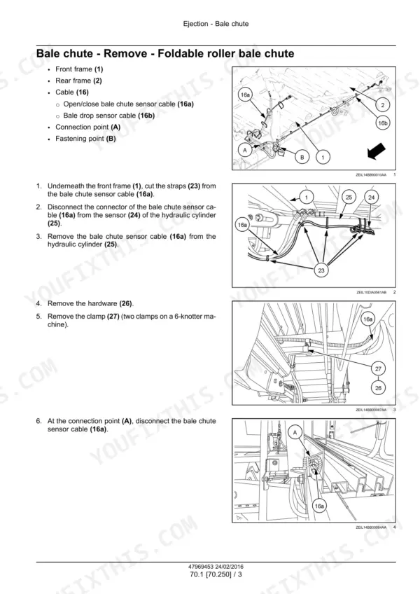
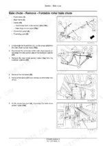
| Bale Chute | 1295-1314 | Foldable Roller Bale Chute Remove, Disassemble, Assemble, Install |
| Grease Lubrication and Oiler System | 1315-1404 | Pump and Reservoir Specification, Grease Lines Manifold, Grease Points Testing, Manifold Block, Oiler System Bleed |
| Shields and Guards | 1405-1419 | Twine Container, Front Shield |
| Special Tool Index | 1420-1421 | Harness Repair Kit, Test Probe Kit, Timer Pin Puller |
Quick Reference Specifications
| Specification | Value | Page |
|---|---|---|
| Gearbox input shaft speed | 1000 RPM | p. 91 |
| Plunger crank drive shaft speed | 48 RPM | p. 91 |
| Bevel gear pair ratio | 7/41 | p. 91 |
| Crank bolt torque, BigBaler 230 and 330 | 1700 N·m (1254 lb ft) | p. 170 |
| Crank bolt torque, BigBaler 340 | 1000 N·m (738 lb ft) | p. 171 |
| Gearbox input shaft bearing rolling torque (4-knotter gearbox) | 2.8 - 3.1 N·m (2.1 - 2.3 lb ft) | p. 96 |
| Stuffer and knotter drive shaft speed | 96 RPM | p. 91 |
| Bale density circuit maximum working pressure | 160 bar (2320 psi) | p. 196 |
| Bale density circulation pressure | 10 - 15 bar | p. 196 |
| Bale density circuit oil volume | ± 12 L | p. 199 |
| Bale density hydraulic oil, standard bale density | HVLP 46 | p. 199 |
| Density valve cartridge torque | 25.8 - 28.5 N·m (19 - 21 lb ft) | p. 200 |
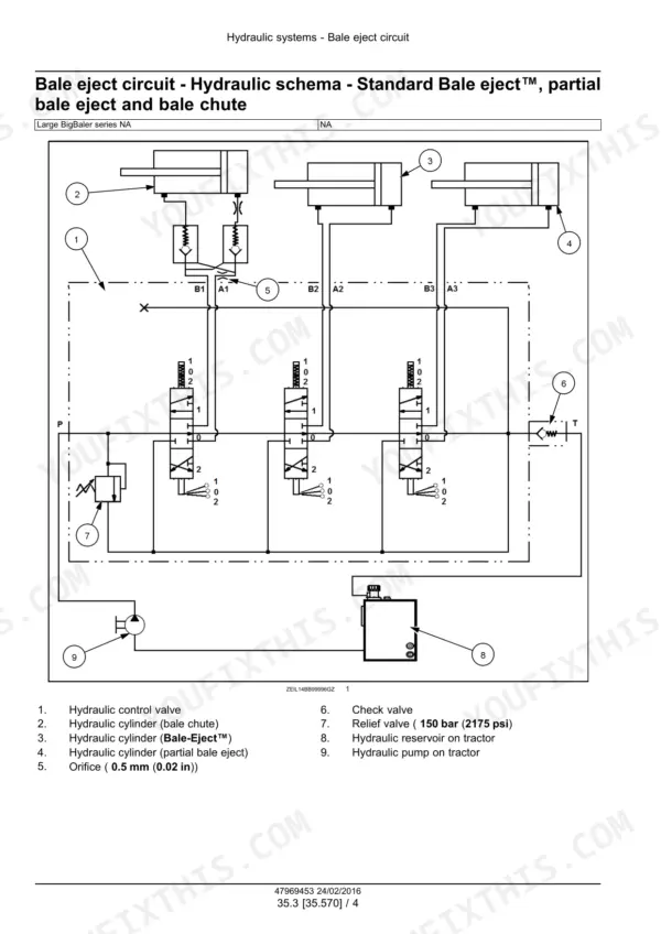
| Bale eject and bale chute relief valve | 150 bar (2175 psi) | p. 224 |
| Grease lubrication pump maximum working pressure | 350 bar (5075 psi) | p. 1318 |
| Grease lubrication pump relief valve | 259 - 293 bar (3756 - 4249 psi) | p. 1318 |
| Grease reservoir capacity | 2 l (0.53 US gal) | p. 1318 |
| Grease | NLGI 2 | p. 1318 |
| Plunger timing distance Y, Standard and Packer Cutter | 229 - 231 mm (9.02 - 9.09 in) | p. 1058 |
| Plunger timing distance Y, Rotor Cutter | 199 - 201 mm (7.83 - 7.91 in) | p. 1058 |
| Twine disc gear backlash | 0.13 - 0.4 mm (0.005 - 0.016 in) | p. 1258 |
New Holland BigBaler 230, BigBaler 330, BigBaler 340 Common Problems This Manual Covers
PTO drive shaft telescoping tubes are bent or deformed
The PTO Drive Shaft troubleshooting table blames an excessive torque peak or a shock load. Do not overload the baler, and never engage the drive under load. Check the torque limiter and the drive shaft lengths. Make sure the drive line does not touch tractor or implement parts.
Manual Section: PTO Drive Shaft p. 50Bale density hydraulic pump is running hot
In Bale Density Circuit fault finding, you check the temperature at the pump and at the other parts in the circuit. If the pump is much hotter than the rest, it has probably failed, so install a new pump. If you bale constantly in hot conditions, switch the density system to thicker HVLP 68 oil.
Manual Section: Bale Density Circuit p. 199Fault code 216-Mistie 2 line open
Broken or missing twine, or a fault in the tensioning system, sets this code. Read the voltage bar graph display. Below 0.5 V, remove and replace mistie detector 2 sensor B-004. Between 0.5 and 7.7 V, check the UCM grounds.
Manual Section: Fault Codes (DTC) p. 681Grease points are getting no grease
The grease points testing in the Grease Lubrication and Oiler System section gives two causes. If the pump does not feed, the reservoir is empty, so fill the reservoir. If the pump element does not rotate, check the wiring harness and replace the greasing pump if needed.
Manual Section: Grease Lubrication and Oiler System p. 1370Frequently Asked Questions
Which New Holland BigBaler models does this service manual cover?
Part number 47969453, 1st edition February 2016, covers the BigBaler 230P Packer Cutter, 230S Standard, 330P Packer Cutter, 330R Rotor Cutter, 330S Standard, 340R Rotor Cutter and 340S Standard. It applies to serial series 4137 and up. It is written for dealer technicians and covers removal, installation, overhaul, adjustment, schematics and fault codes. The manual refers gearbox oil fill and slip clutch spring settings to the operator's manual. p. 2
What are the BigBaler 230, 330 and 340 main gearbox and drive specs?
The input shaft runs at 1000 RPM through a 7/41 bevel gear pair. The plunger crank drive shaft turns at 48 RPM, the packer/rotor and pickup drive shaft at 200 RPM, and the stuffer and knotter drive shaft at 96 RPM. Crank bolt torque is 1700 N·m (1254 lb ft) on the 230 and 330, and 1000 N·m (738 lb ft) on the 340. The flywheel slip clutch works with the flywheel shearbolt to protect the PTO drive shaft and the main drive. p. 91
What are the BigBaler bale density hydraulic pressures and oil?
Maximum working pressure is 160 bar (2320 psi), and circulation pressure is 10 - 15 bar. The whole circuit holds about ± 12 L of oil. Run HVLP 46 for standard bale density and HVLP 68 for thick bale density. Torque the density valve cartridge to 25.8 - 28.5 N·m (19 - 21 lb ft). The bale eject and bale chute relief valve is set at 150 bar (2175 psi). p. 196
What knotter adjustments does the BigBaler service manual give?
The knotter section covers knotter drive system timing, knotter gearbox overhaul, the needle yoke and trip arm adjustment. It gives separate knotter stack dimensions for the 230/330 and for the 340, plus knotter assembly. Twine disc gear backlash is 0.13 - 0.4 mm (0.005 - 0.016 in). Plunger timing distance Y is 229 - 231 mm (9.02 - 9.09 in) on Standard and Packer Cutter balers. On Rotor Cutter balers it is 199 - 201 mm (7.83 - 7.91 in). p. 1258
What is inside this manual: schematics, fault codes, troubleshooting?
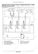
The electrical schematic sheets cover power distribution, UCM power, bale length, moisture control, the camera kit and more. Hydraulic schemas cover the bale density, knife positioning, bale eject and tandem auto-steer lock circuits. The FAULT CODES (DTC) section lists possible failure modes and solutions for each code. You also get sensor tests, PTO drive shaft troubleshooting, bale density fault finding, grease lubrication tests and a special tool index. p. 676





Reviews
There are no reviews yet.