
Part of the New Holland Repair Manuals.
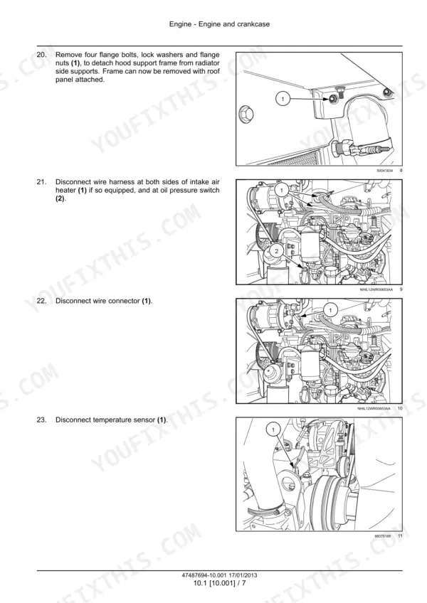
Fits the New Holland H8040 self-propelled windrower from PIN YCG667001 and above, with or without a draper. Part number 47487694, 1st edition January 2013, covers the NEF 4-cylinder turbo diesel, the hydrostatic drive, the header drive pump, hydraulics, electrics and the cab.
It gives transmission to flywheel housing torque as 113 N·m (83 lb ft), plus the relief settings, the DTC tables, schematic frames 01 to 63 and fold-out schematics for both builds.
What's Inside This New Holland H8040 Manual
| System | Pages | Key Topics |
|---|---|---|
| Introduction | 1-38 | Safety Rules, Minimum Tightening Torques, Standard Torque Data for Hydraulics, Hydraulic Contamination, Capacities, Biodiesel Fuels, Product Identification |
| Engine | 39-116 | Engine and Crankcase, Air Cleaner, Fuel Tank, Fuel Injection System Bleed, Intake and Exhaust Manifolds, Engine Cooling System, Radiator |
| Front Axle System | 117-146 | Final Drives, Special Tools, Driven Gears and Shaft, Front Mechanical Drive |
| Rear Axle System | 147-208 | Non-Powered Rear Axle, Non-Suspended Rear Axle, Suspended Axle, Axle Extension |
| Hydrostatic Drive | 209-302 | Shuttle Spool Valve, Relief Valve, Hydrostatic Transmission, Pressure Test, Pump and Motor Components, Charge Pump |
| Power Take-Off (PTO) | 303-316 | Hydraulic Pump Drive, Header Drive Pump |
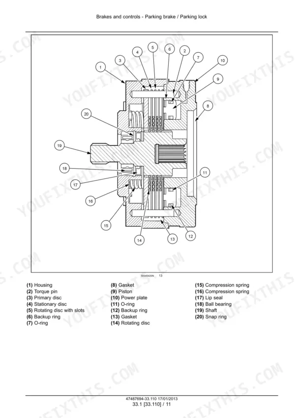
| Brakes and Controls | 317-338 | Parking Brake, Parking Lock, Bleed |
| Hydraulic Systems | 339-542 | Hydraulic Symbol, Hydraulic Schema, Header Lift, Header Tilt, Pump Control Valves, Fixed Displacement Pump, Charge Pump, Reservoir, Accumulator, Cutter Control Circuit, Draper Header Hydraulic Drive |
| Steering | 543-554 | Steering Control, Steering Wheel |
| Wheels | 555-564 | Rear Wheels, Non-Suspended Rear Axle |
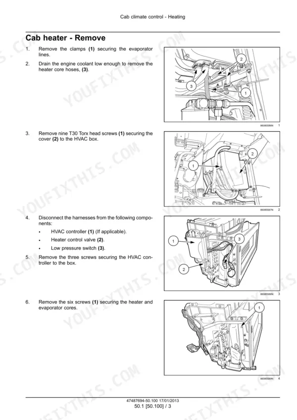
| Cab Climate Control | 565-674 | Heating, Cab Heater, Heater Control Valve, Ventilation, Blower Motor, Air Conditioning, Refrigerant |
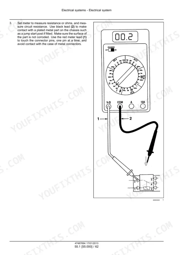
| Electrical Systems | 675-812 | Component Identification, UCM Module, Sensors, Relays, Solenoids, Calibrations, Short to Ground |
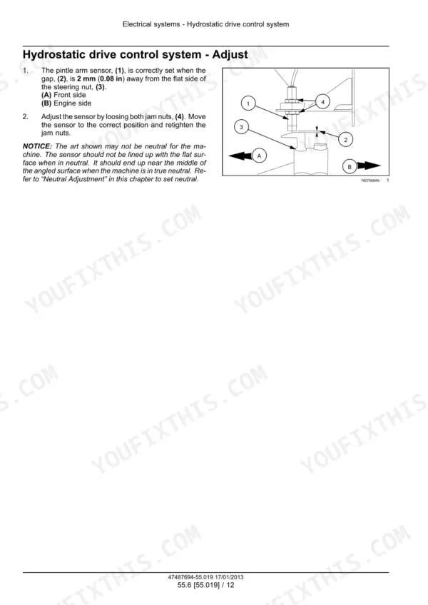
| Engine and Drive Electrical Controls | 813-904 | Fuel Injection System, Blow-By Solenoid, EGR Bypass Solenoid, Hydrostatic Drive Control System, Parking Brake Electrical System, HVAC Control System |
| Harnesses, Connectors and Electrical Schematics | 905-1130 | Electrical Schematic Frame, Starting System, Power Distribution System |
| Starting, Lighting and Cab Electrical Controls | 1131-1244 | Engine Starting System, Starter Motor, External Lighting, Cab Controls, Wiper, Reel Speed Synchronization, Merger, Header Height Control, Rotary Screen |
| Fault Codes (DTC) | 1245-1498 | Fault Codes, Ucm, ECU |
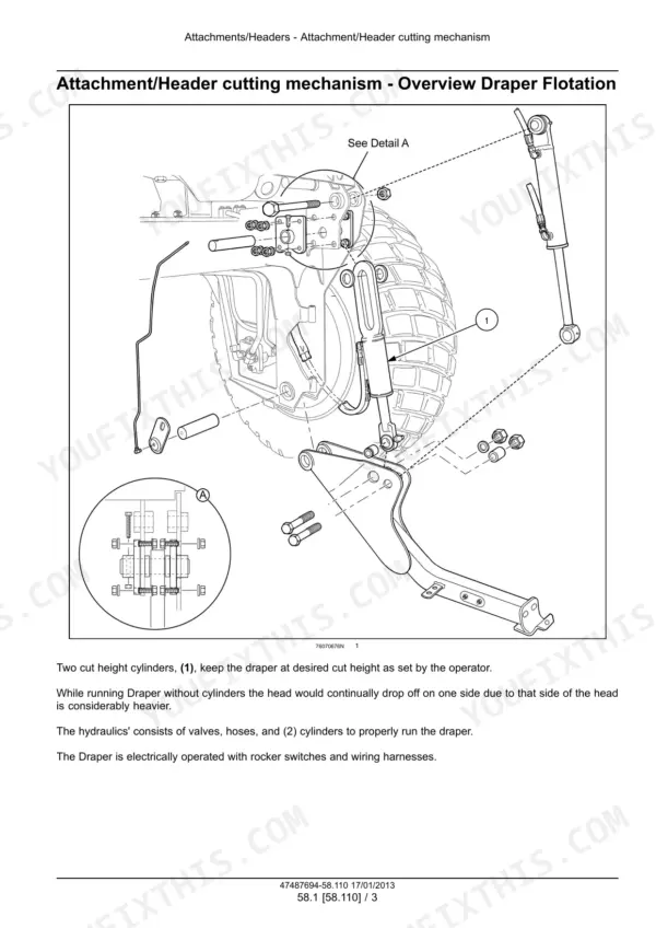
| Attachments/Headers | 1499-1528 | Header Cutting Mechanism, Draper Flotation, Sickle Header Drive Adapter Kit, Swath Roller Hitch |
| Platform, Cab, Bodywork, and Decals | 1529-1612 | Operator Seat, Seat Compressor, Cab, Cold Start Kit, Cab Interior, Seat Restraints, Cab Doors |
| Schemas Index and Special Tool Index | 1613-1616 | Wire Connectors, Component Diagram, Special Tool |
| Fold-Out Electrical and Hydraulic Schematics | 1617-1633 | Non-Draper Equipped, Draper Equipped |
Quick Reference Specifications
| Specification | Value | Page |
|---|---|---|
| Engine | NEF 4-cyl diesel turbocharged w/ charge air cooler | p. 30 |
| Rated engine power | 94 kW (126 Hp) | p. 30 |
| Rated engine speed | 2300 RPM | p. 30 |
| Peak engine torque | 521 N·m (384 lb ft) @ 1400 RPM | p. 30 |
| Engine displacement | 4.5 l (274 in³) | p. 30 |
| Firing order | 1-3-4-2 | p. 46 |
| Engine oil capacity with filter | 10.4 l (11 US qt) | p. 33 |
| Fuel tank capacity | 454 l (120 US gal) | p. 33 |
| Hydraulic reservoir capacity | 52.4 l (13.8 US gal) | p. 33 |
| Cooling system capacity | 26 l (27 US qt) | p. 33 |
| Fuel pressure between filter and high pressure pump | 5 bar (72 psi) minimum | p. 89 |
| Hydrostatic pump relief setting, system warm | 383.4 bar (5560 psi) | p. 231 |
| Charge pump relief setting | 20.0 bar (290 psi) | p. 231 |
| Hydrostatic case pressure, continuous | 1.7 bar (25 psi) max. | p. 231 |
| High idle speed | 2450 RPM | p. 30 |
| Hydrostatic transmission to flywheel housing torque | 113 N·m (83 lb ft) | p. 232 |
| Rear axle extension bolt torque | 960 N·m (708 lb ft) | p. 156 |
| Rear tire inflation pressure, non-suspended axle | 138 kPa (20 psi) | p. 155 |
| Accumulator nitrogen precharge | 5516 kPa (800 psi) | p. 523 |
| A/C compressor oil | 270 ml (9.13 US fl oz) SP-15 PAG Oil | p. 604 |
New Holland H8040 Common Problems This Manual Covers
Engine overheats
The Engine section's cooling system chart takes you through the causes in order. Check for leaking or collapsed hoses and a radiator cap that doesn't seal. Look at the fins, the thermostat, belt adjustment, the coolant pump and the head gasket. Tighten or replace hoses, renew the cap or thermostat and blow the fins clean with compressed air. Check the tensioner and belt, then reverse flush the cooling system.
Manual Section: Engine p. 113Noisy charge pump or high oil temperature in the hydrostatic drive
The Hydrostatic Drive section's charge pump chart points at low oil supply, oil that is too heavy or too light, and a plugged filter or suction line. Contaminated oil or a wrongly set relief valve also cause it. Fill the reservoir, clean the filters and lines, then drain and refill with clean oil of the right viscosity. Finally, set the relief to the correct pressure.
Manual Section: Hydrostatic Drive p. 299Windrower will not shift into high range (2-speed motor only)
Follow the Hydrostatic Drive test sequence in order. Confirm power at the two-speed solenoid and replace the coil if it reads over 10 ohms. Check charge pressure, a stuck solenoid valve, and the O rings and backup rings. Read the two-speed valve output, which should be 1999 kPa (290 psi). Replace the solenoid valve if it is below 1379 kPa (200 psi), then check pressure going into the motors.
Manual Section: Hydrostatic Drive p. 259Header drive pump noisy from cavitation, fluid overheats or foams
The Power Take-Off (PTO) header drive pump chart lists the suspects. Fluid may be too heavy or too thin, or the filters may be plugged. The suction line may be plugged or undersized, the level low, air leaking in, or the relief set wrong. Change to the correct viscosity fluid and clean or replace the filters. Tighten fittings, replace seals and top up. Case pressure must not exceed 275.8 kPa (40 psi) at full operation.
Manual Section: Power Take-Off (PTO) p. 314Frequently Asked Questions
Which New Holland H8040 windrower does this service manual cover?
The H8040 self-propelled windrower from PIN YCG667001 and above, both non-draper and draper equipped. It is New Holland part number 47487694, 1st edition January 2013. It is the dealer workshop book, covering removal, installation, overhaul, tests, schematics and fault codes. p. 1
What are the H8040 engine specifications?
It has an NEF 4-cylinder turbocharged diesel with a charge air cooler. Displacement is 4.5 l (274 in³) and the firing order is 1-3-4-2. It makes 94 kW (126 Hp) at a rated 2300 RPM, with high idle at 2450 RPM. Peak torque is 521 N·m (384 lb ft) at 1400 RPM. Fuel pressure between the filter and the high pressure pump should be at least 5 bar (72 psi). p. 30
What are the H8040 hydrostatic drive pressure settings?
Hydrostatic pump relief is 383.4 bar (5560 psi) with the system warm. Charge pump relief is 20.0 bar (290 psi). Continuous case pressure must stay at 1.7 bar (25 psi) max. Transmission to flywheel housing torque is 113 N·m (83 lb ft), and the accumulator takes a 5516 kPa (800 psi) nitrogen precharge. p. 231
What are the H8040 fluid capacities?
Engine oil with filter is 10.4 l (11 US qt) and the fuel tank holds 454 l (120 US gal). The hydraulic reservoir takes 52.4 l (13.8 US gal) and the cooling system 26 l (27 US qt). The final drives take 1.75 l (1.8 US qt) and the flywheel gearbox 1.9 l (2.0 US qt). p. 33
What is inside this manual: schematics, fault codes, troubleshooting?
It has electrical schematic frames 01 to 63, covering starting, driveline propulsion, the communications network, power distribution and more. There are fold-out electrical schematics for non-draper and draper machines, plus a fold-out hydraulic schematic. The FAULT CODES (DTC) section gives the cause, possible failure modes and solution for UCM, ECU and XCM codes. Troubleshooting charts cover engine cooling, the charge pump, the header drive pump, air conditioning and header functions. p. 1245





Reviews
There are no reviews yet.