Part of the New Holland Repair Manuals.
This is the New Holland factory service manual for the CR6080 combine, part number 47454930, dated 25/03/2013. The cover prints two applicability lines: CR6080 [JHFY6080JCJ301196 - ] and CR6080 [JHFY6080LBJ200440 - ]. It runs from the main gearbox and S90 hydrostatic pump through the rotor, concave, sieves and unload drive.
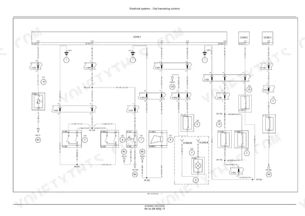
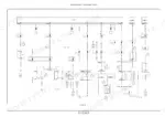
It includes hydraulic circuit diagrams, electrical schematic frames and fault codes by control module.
What's Inside This New Holland CR6080 Manual
| System | Pages | Key Topics |
|---|---|---|
| Cover and Contents | 1-6 | Model Applicability, PIN Ranges, Part Number, Publication Date, General Contents |
| Introduction | 7-20 | Foreword, Personal and Machine Safety, Basic Instructions, Fastener Torque, Roller Chain Wear Tables |
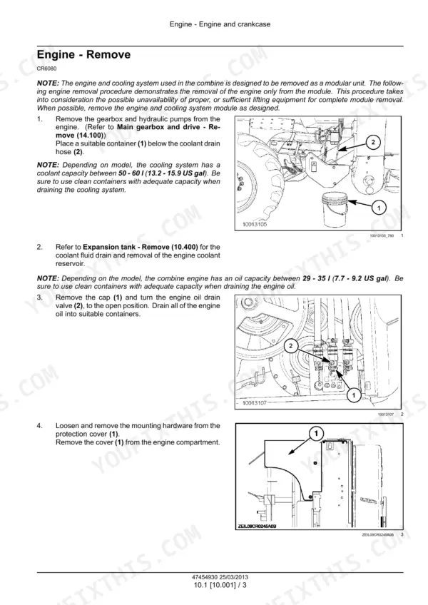
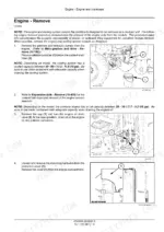
| Engine | 21-82 | Engine Removal and Installation, Engine Troubleshooting, Fuel Injection, Air Cleaners, Cooling System, Air Compressor |
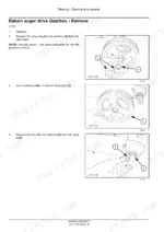
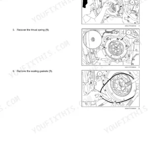
| Main Gearbox and Drive | 83-144 | Main Clutch, Unload Clutch, Main Gearbox, Dampener, Torque Values, Bearing Shimming |
| Transmission | 145-228 | Mechanical Transmission, External Shift Controls, Gearbox Internal Components, Differential |
| Front Axle System | 229-248 | Final Drive Torque, Gear Ratio, Output Shaft Preload, Input Shaft End Play, Wheel Studs, Final Drive Assembly |
| Hydrostatic Drive | 249-370 | Hydrostatic Control, Reservoir and Cooler, Pump and Motor, Hydrostatic Transmission, Powered Rear Axle, Pressure Testing, Troubleshooting |
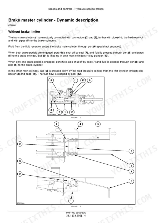
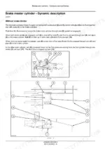
| Brakes and Controls | 371-410 | Hydraulic Service Brakes, Brake Master Cylinder, Brake Disks, Brake Caliper, Parking Brake |
| Hydraulic Systems | 411-516 | High Pressure Circuit, Low Pressure Circuit, CCLS Pump, Header Height, Header Leveling, Header Reverser, Traction Variator |
| Steering | 517-538 | Steering Control, Steering Valve, Hydraulic Control Components, Autoguidance Steering |
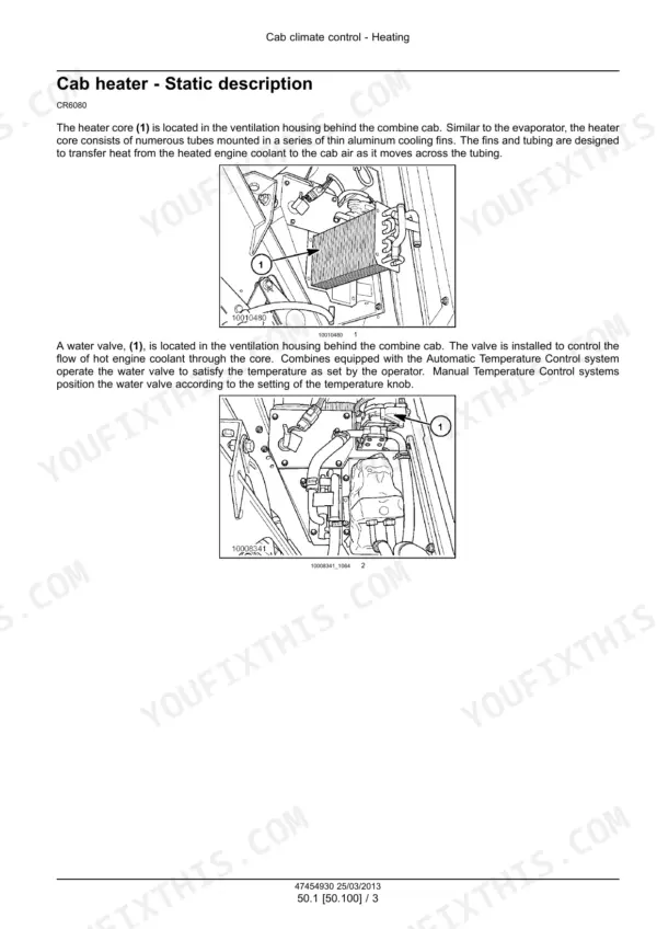
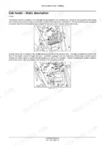
| Cab Climate Control | 539-628 | Heating, Ventilation, Air Conditioning, Refrigerant Recovery and Refilling, Leak Testing, Compressor and Condenser |
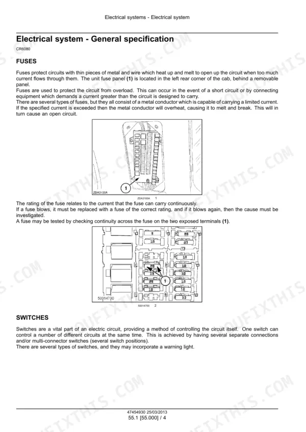
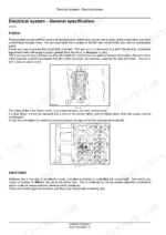
| Electrical Systems - Power, Modules and Cab Controls | 629-930 | Harnesses and Connectors, Starting and Charging, Electronic Modules, Hydrostatic Controls, Cab Controls, Hydraulic Control, HVAC Controls |
| Electrical Systems - Harvesting Controls | 931-1238 | Header and Feeder Controls, Residue Handling, Threshing and Cleaning Controls, Harvest Material Flow, Precision Farming and GPS, Autoguidance, Lighting and Instruments |
| Fault Codes - Module and CAN | 1239-1731 | Module Offline, CAN Communications, CM1 Sensors and Outputs, CM2 Transmission Controls, CM3 Cleaning Controls, Circuit Testing |
| Fault Codes - Engine Controller | 1732-1934 | ECU Key Switch Input, Grid Heater, Fuel Injectors, Temperature Sensors, Pressure Sensors, Internal Controller Failures |
| Fault Codes - Header and Console | 1935-2134 | Header Height Control Feeder Angle Sensor, Header Height Controls, RHM Console Switches, Multi Function Handle, Emergency Stop, Fault Code Index |
| Product Feeding | 2135-2218 | Floating Roll and Feed Chain, Feeder Housing, Feeder Shafts, Feeder Drive, Feeder Reverser, Rotor |
| Threshing | 2219-2348 | Threshing Mechanism Drive, Rotor, Rotor Gearbox, Rotor Housing, Rotor Variator, Concave, Concave Conveyor Plate, Concave Control |
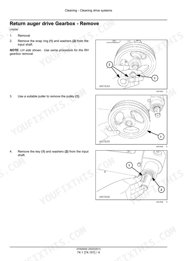
| Cleaning | 2349-2428 | Cleaning Drive, Grain Pan, Clean Grain and Return Cross Augers, Fan Housing, Fan Drive, Tailings Return |
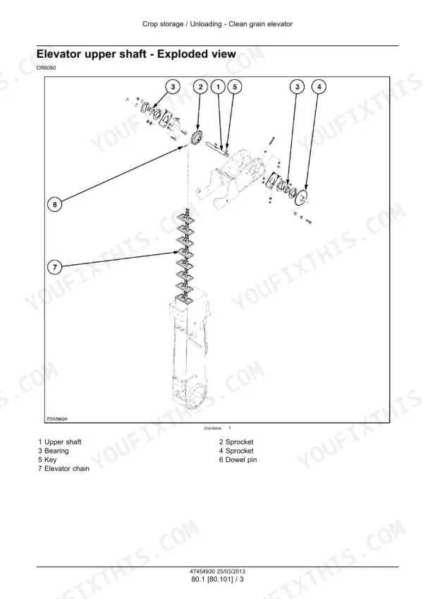
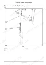
| Crop Storage and Unloading | 2429-2516 | Clean Grain Elevator, Grain Tank, Unload Drive, Grain Tank Unload |
| Platform, Cab, Bodywork and Decals | 2517-2570 | Operator Platform, Protections and Footboards, Pneumatically-Adjusted Seat, Special Tool Index |
Quick Reference Specifications
| Specification | Value | Page |
|---|---|---|
| Engine oil capacity (depending on model) | 29 - 35 l (7.7 - 9.2 US gal) | p. 40 |
| Cooling system capacity (depending on model) | 50 - 60 l (13.2 - 15.9 US gal) | p. 41 |
| A/C refrigerant capacity (R-134a) | 3.6 kg (7.94 lb) | p. 586 |
| Thresher shaft spur gear cap screws torque | 110-120 N·m ( 81-88 ft. lbs.) | p. 88 |
| Hydraulic pump drive housing torque | 190-210 N·m ( 140-155 ft. lbs.) | p. 88 |
| Engine flange cap screws torque | 80-90 N·m ( 59-66 ft. lbs.) | p. 88 |
| Mechanical transmission nut on drive shaft torque | 150-170 N·m ( 111-125 ft. lbs.) | p. 149 |
| Final drive to traction beam bolt torque | 670 Nm ( 495 ft.lbs) | p. 233 |
| Wheel nuts torque | 610-732 Nm ( 450 - 540 ft.lbs ) | p. 233 |
| Final drive gear ratio | 1/13.09 | p. 233 |
| Hydrostatic pump rated speed (S90) | 3100 rpm | p. 274 |
| Hydrostatic pump maximum speed (S90) | 3400 rpm | p. 274 |
| Charge pump pressure | 38 bar (551 psi) | p. 274 |
| Brake manifold pressure setting | 140 bar (2030 psi) | p. 274 |
| Hydrostatic transmission pressure limiter | 420 bar ( 6090 psi) | p. 311 |
| Hydrostatic transmission relief valve | 450 bar ( 6525 psi) | p. 311 |
| Main hydraulic pump standby pressure | 21 bar ( 305 psi) | p. 439 |
| Steering pressure | 186 bar ( 2700 psi) | p. 439 |
| Right-hand rotor gearbox mounting bolts torque | 94 - 106 Nm (69 - 78 lb ft) | p. 2277 |
| Cleaning fan driven sheave locking nut (outer) torque | 200 N·m ( 147.6 ft. lbs.) | p. 2401 |