
Part of the New Holland Repair Manuals.
Seeding is underway, the monitor just flagged a meter motor stall and the cart is half full at the end of the field. This is the New Holland service manual for the P2350, P3440, P3550, P4460, P4580, P4760 and P4950 air carts. It is part number 47827462, 1st edition, April 2017.
It covers tow-behind and tow-between carts, single and double shoot, all three auger setups and the auxiliary tank. Specifications are printed where the work is done, such as 931 N·m +/- 140 N·m for the rear dual wheel bolts.
The sections go system by system: fan motors, metering, UCM, hydraulic schemas, wiring sheets, brakes and alternator. A fault code or a fan leak takes you straight to its chapter.
What's Inside This New Holland P2350–P4950 Manual
| System | Pages | Key Topics |
|---|---|---|
| Introduction and Safety | 1-68 | Foreword, Safety Rules, Safety Signs, Shop and Assembly Instructions, Electrical Testing, Hydraulic Contamination, Auger Remote Operation |
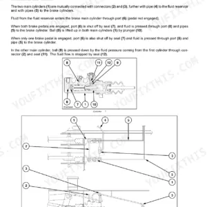
| Front Axle, Rear Axle and Brakes | 69-116 | Non-Powered Front Axle, Rear Axle Removal and Installation, Dual Wheels, Wheel Bolt Torque, Brake Calipers, Brake Pump and Block, Brake Bleeding |
| Hydraulic Systems and Hydraulic Schemas | 117-175 | Hydraulic Overview, Component Diagram, Hydraulic Symbols, Single Shoot and Double Shoot Circuits, Manual Auger Circuits, Auxiliary Tank Circuits, Hydraulic Troubleshooting |
| Hydraulic Seeding Fan System | 176-187 | Fan Motor Detailed View, Motor Removal, Disassembly and Assembly, Motor Replacement, Oil Leak Diagnosis |
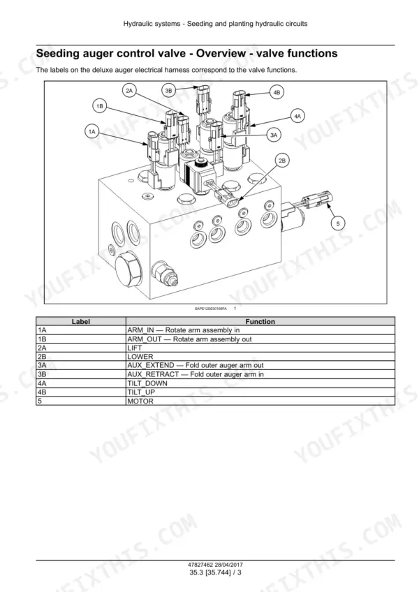
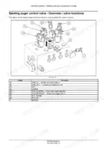
| Auger and Auxiliary Fill Hydraulic Circuits | 188-236 | Auger Control Valve, Hydraulic Hose Connections, Manual Auger Valve, Auger Cylinders, Auger Motor Service, Flow Divider, Auxiliary Feeder and Fan Motors |
| Frames, Hitch and Wheels | 237-272 | Drawbar Configuration, Hitch Inspection, Rear Wheel Options, Tire Spacing, Wheel Torque, Tire Pressure, Caster Wheel Installation, Caster Brake Adjustment |
| Electrical System - Alarms and Charging | 273-293 | Operator Alarms, Tank Level Alarms, Fan RPM Alarms, Meter Motor Alarms, Tank Pressure Alarms, Alternator Charging Diagnosis |
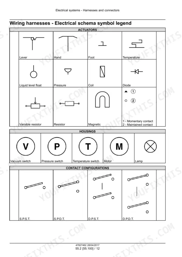
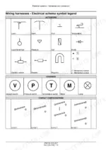
| Electrical Schematic Sheets | 294-535 | Electrical Symbol Legend, 12V Power, CAN Bus, Tank Pressure Sensors, Meter Motor Power, LIN Bus, Battery Relays and Fuse Box, Transport Lighting |
| Wire Connectors and Component Diagrams | 536-1050 | Component Diagrams, Connector Views, Connector Part Numbers, Pin Assignments, Wire Colors and Sizes, UCM and Tank Motor Connectors, Lighting and Brake Connectors |
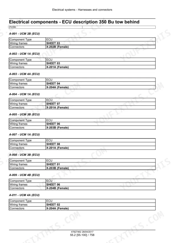
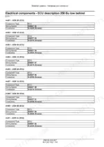
| Electrical Component Descriptions | 1051-1143 | ECU Descriptions, Sensor Descriptions, Fuse Descriptions, Ground Descriptions, Power Outlets, Switch Descriptions, Brake Controller Components |
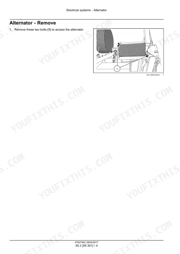
| Alternator | 1144-1157 | Alternator Hydraulic Motor, Operating Pressures and Speeds, Alternator Removal, Drive Removal and Assembly, Belt Adjustment |
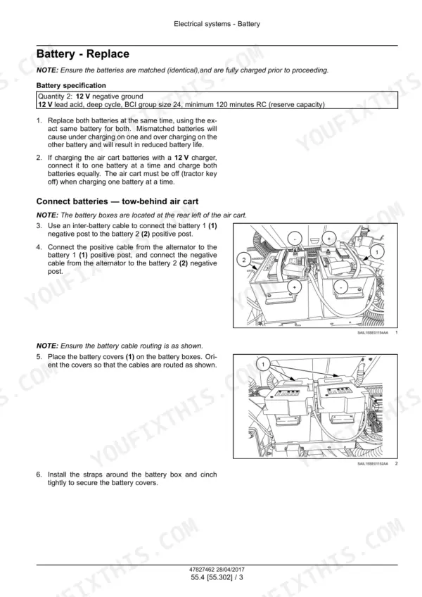
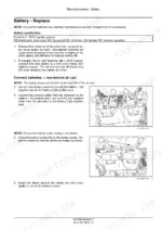
| Battery | 1158-1163 | Battery Specification, Matched Battery Replacement, Individual Battery Charging, Tow-Behind and Tow-Between Battery Connections |
| External Lighting | 1164-1171 | Transport Lighting Operation, Turn and Brake Lighting Logic, Seven-Terminal Connections, Beacon Bulb Replacement |
| Seeding Control System | 1172-1255 | Rate Meter Motor Technical Data, Motor Position Assignment, Flow Monitoring, Tank Sensor Cleaning, Pressure Sensor Testing, Fan and Wheel Speed Sensor Clearance |
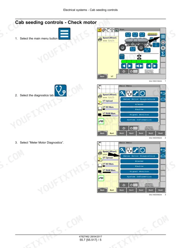
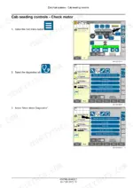
| Cab Seeding Controls | 1256-1275 | Calibration Switch, Motor Diagnostics, Alarm and Fault Checks, Signal Monitor, Software Version Checks, Work Switch Adjustment, Problem Solving |
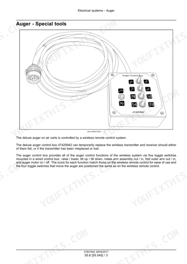
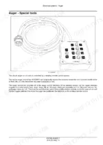
| Auger Electrical Controls | 1276-1299 | Auger Control Overview, Wiring Harness Component Diagram, Auger Electrical Schematic Sheets, Remote Receiver Operation, Remote Calibration, Problem Solving |
| Electronic Modules (UCM) | 1300-1303 | UCM Power and Grounds, CAN Bus Connections, CAN Termination, EST Programming, Electromagnetic Interference, UCM Replacement Diagnosis |
| Precision Farming System | 1304-1325 | Section Control, Universal Tractor Harness, GPS Connections, Connector Diagrams, Splice Table, Power and RS232, CAN Bus and Display Pins |
| Fault Codes (DTC) | 1326-1598 | Air Cart UCM Fault Codes, Meter Motor Faults, Brake ECU Faults, Sensor Power Faults, Ground Speed and Fan Speed Faults, Tank Sensor Faults, Flow Gateway ECU Faults |
| Metering System | 1599-1632 | Product Metering Operation, Meter Cartridge and Roller Installation, Meterbank Timing, Meter Clean-Out, Inspection, Cleaning and Replacement |
| Seeding - Auger, Conveyor, Fan and Air Distribution | 1633-1696 | Deluxe Auger Service Position, Auger Lubrication, Emergency Control Box, Tank Lid Tightening, Conveyor Belt Service, Seeding Fan Service, Auxiliary Fill Troubleshooting, Air Distribution |
| Platform, Bodywork, Decals and Special Tools | 1697-1717 | Safety Decals, Operator Platform, Platform Support Link, Protections and Footboards, Covers, Special Tool Index |
Quick Reference Specifications
| Specification | Value | Page |
|---|---|---|
| Brake caliper maximum operating pressure (P4760, P4950) | 15515 kPa (2250 psi) | p. 104 |
| Brake block hydraulic filter maximum flow rate (P4760, P4950) | 75 L/min (20 US gpm) | p. 109 |
| Seeding fan motor displacement | 16 cm³/rev (1 in³/rev) | p. 178 |
| Seeding fan motor maximum operating pressure | 20684 kPa (3000 psi) | p. 178 |
| Manual auger hydraulic cylinder | 2 in bore x 8 in stroke 3000 psi | p. 199 |
| Auxiliary tank fill fan motor displacement (P3550, P4580, P4760, P4950) | 9.8 cm³/rev (0.6 in³/rev) | p. 212 |
| Auxiliary tank fill fan motor maximum operating speed | 6000 RPM | p. 212 |
| Auxiliary tank fill fan motor maximum operating pressure | 20684 kPa (3000 psi) | p. 212 |
| Wheel bolt torque - front caster wheels | 169 N·m +/- 26 N·m ( 125 lb ft +/- 19 lb ft) | p. 86 |
| Wheel bolt torque - front steered wheels | 441 N·m +/- 66 N·m ( 325 lb ft +/- 49 lb ft) | p. 86 |
| Wheel bolt torque - rear single wheels | 441 N·m +/- 66 N·m ( 325 lb ft +/- 49 lb ft) | p. 86 |
| Wheel bolt torque - rear dual wheels | 931 N·m +/- 140 N·m ( 687 lb ft +/- 103 lb ft) | p. 86 |
| Alternator drive motor normal operating speed | 4250 RPM | p. 1146 |
| Alternator drive motor maximum speed | 4400 RPM | p. 1146 |
| Rate meter drive motor speed range | 4 - 95 RPM | p. 1175 |
| Rate meter drive motor operating voltage | 22 - 32 V | p. 1175 |
| Batteries | 2: 12 V negative ground | p. 1160 |
| Battery type | 12 V lead acid, deep cycle, BCI group size 24, minimum 120 minutes RC (reserve capacity) | p. 1160 |
| Maximum rate per primary line (urea) | 21.8 kg/min (48 lbs/min) | p. 1666 |
| Maximum rate per primary run (wheat) | 23.6 kg/min (52 lbs/min) | p. 1666 |
New Holland P2350–P4950 Common Problems This Manual Covers
Fault 401TMM-07: meter motor stall during seeding
The Fault Codes (DTC) section traces 401TMM-07 to a meter roller binding on something in the cartridge, like a rock or a fertilizer lump. Clean out the cartridge, reinstall it, return to field operation and monitor for a recurring fault. The Metering System section covers cartridge and roller installation and meterbank timing.
Manual Section: Electrical systems - FAULT CODES p. 1333Oil leaking at the seeding fan motor
Fan motor problem solving in the Hydraulic Seeding Fan System section starts with loose hose fittings, so check and tighten those before you take anything apart. If the motor itself is leaking, the same section has a detailed view and covers removal, disassembly, assembly and replacement.
Manual Section: Motor - Problem solving p. 186Hydraulic oil is too hot
Hydraulic troubleshooting in the Hydraulic Systems section names low fluid level in the tractor as a cause of hot oil. The remedy it gives is to maintain adequate oil levels in the tractor. The same section has the single shoot, double shoot, auger and auxiliary tank hydraulic schemas for tracing each circuit on the cart.
Manual Section: Hydraulic systems - Troubleshooting p. 173Alternator not charging the air cart batteries
The 24V power problem solving page starts at the alternator connector: unplug it and check that greater than 12 V is present on the center pin. Insufficient alternator RPM can also stop charging, and the alternator needs to turn at 1500 RPM (lower fan speed of approximately 2100 RPM) to begin to charge. Then check the voltage on both batteries, since a difference of more than 0.7V may indicate a bad battery.
Manual Section: Electrical system - Problem solving 24V power p. 291Frequently Asked Questions
Which air carts does the New Holland P2350 to P4950 service manual cover?
It covers seven models: P2350, P3440, P3550, P4460, P4580, P4760 and P4950, under part number 47827462, April 2017. The wiring sheets are split by configuration, including tow-behind and tow-between versions of the P2350. Some hydraulic schemas, such as the 350 Bu tow behind single shoot with manual auger, are marked as starting at YGS069043, so match it to your cart by model, layout and serial. p. 274
What is the maximum operating pressure of the seeding fan motor on the New Holland P-series air cart?
The lower and upper seeding fan motors are rated at 20684 kPa (3000 psi) maximum, with a displacement of 16 cm³/rev (1 in³/rev). On the P3550, P4580, P4760 and P4950, the auxiliary tank fill fan motor has the same 3000 psi limit. It runs 9.8 cm³/rev (0.6 in³/rev) with a 6000 RPM maximum. p. 178
What batteries does the New Holland P-series air cart use?
It uses two 12 V negative ground batteries. The spec is 12 V lead acid, deep cycle, BCI group size 24, with at least 120 minutes reserve capacity. The Battery section covers matched replacement, charging each battery on its own, and the hookup for tow-behind and tow-between carts. p. 1160
What is the wheel bolt torque for the rear dual wheels on the New Holland P-series air cart?
Rear dual wheels take 931 N·m +/- 140 N·m (687 lb ft +/- 103 lb ft). Rear singles and front steered wheels take 441 N·m +/- 66 N·m (325 lb ft +/- 49 lb ft). Front caster wheels drop to 169 N·m +/- 26 N·m (125 lb ft +/- 19 lb ft). p. 86
Does the New Holland P-series air cart service manual include wiring diagrams, hydraulic schemas and fault codes?
Yes. There are electrical schematic sheets for each configuration with a symbol legend, plus connector tables with Pin, Wire and Color-Size columns. Hydraulic schemas cover single shoot, double shoot, auger and auxiliary tank layouts. The UCM fault code section includes 401TMM-07 - Tank T - Motor MM - Motor Stall detected, with causes and corrective steps for each code. p. 307







Reviews
There are no reviews yet.