

Part of the New Holland Repair Manuals.
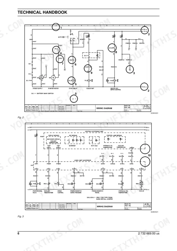
Fixing the hydrostatic drive on your New Holland Construction LW 80 Wheel Loader requires the right data, and this 541-page technical manual (OEM #73179332) gives you every factory procedure. Open the file to find complete hydraulic schematics for the lifting and steering circuits, alongside detailed wiring diagrams for the entire electrical system. You get step-by-step teardown instructions for the axles, brakes, and control blocks, plus dedicated troubleshooting charts to track down stubborn faults. Verify your boom performance by checking the empty bucket lifting time against the factory 6.3-second standard, then confirm the cooling system is topped off with exactly 18.5 liters of fluid. Stop wasting hours bleeding brake valves blind. Grab this indexed PDF on your tablet, find the exact schematics you need, and get that loader pushing dirt again.
What's Inside This New Holland LW 80 Manual
| System | Pages | Key Topics |
|---|---|---|
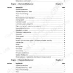
| General | 3-15 | Safety Instructions, Warnings and Symbols, Repair Work, Accumulators, Engine Safety, Welding Operations |
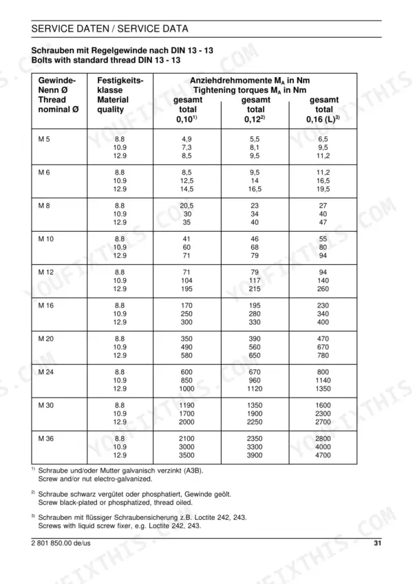
| Service Data | 16-55 | Si and Additional Units, Conversion Tables, Calculation Examples, Tightening Torques, Temperature Units |
| Engine | 56-70 | Engine Specifications, Axles and Transmission Gears, Travel Speeds, Hydraulic System Data, Service Fluids, Approximate Weights |
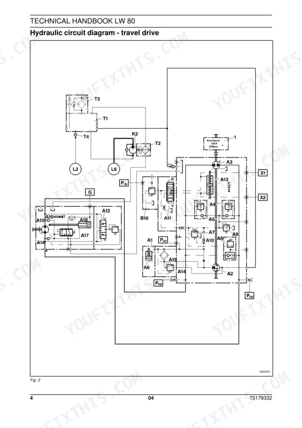
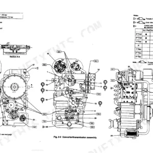
| Travel Drive | 71-97 | Hydraulic System Safety, Circuit Diagrams, Hydrostatic Drive Principle, High Pressure Adjustment, Repair Instructions |
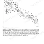
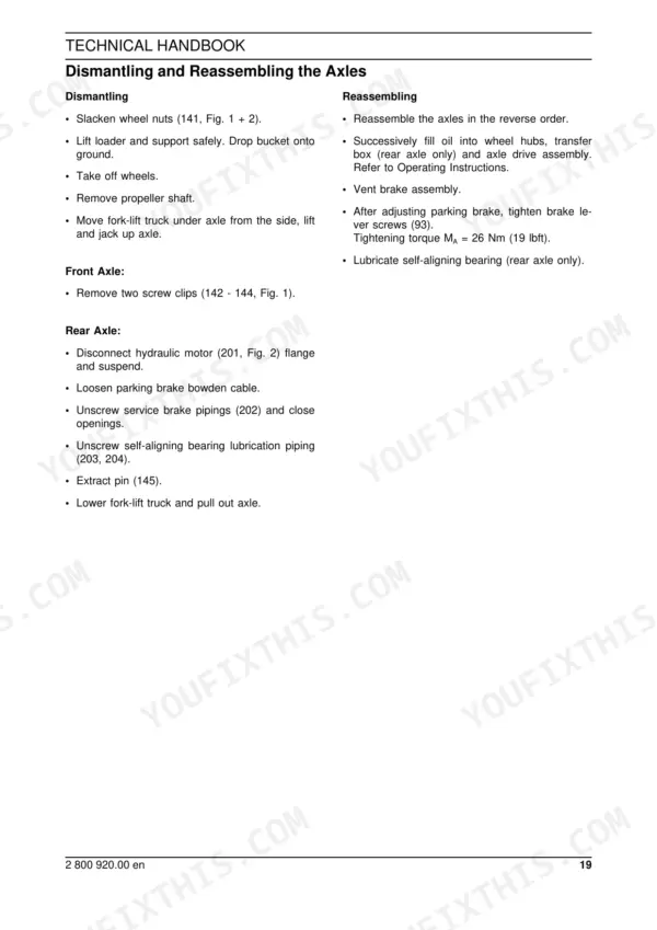
| Axles | 186-280 | General Design, Maintenance, Filling Quantities, Dismantling Procedures, Assembling Procedures, Tightening Torques |
| Steering | 281-299 | Hydraulic System Safety, Circuit Diagrams, Steering System Overview, Functional Description, Priority Valve, Steering Cylinder, Steering Valve |
| Brakes | 300-318 | Safety Instructions, Braking System Circuit, Functional Description (Service, Auxiliary, Parking Brake), Accumulator Charging Valve, Pedal-Type Brake Valve, Bleeding System |
| Hydraulic System (Working Hydraulics & Cooling) | 319-347 | Safety Instructions, Working Hydraulics Circuit, Functional Description, Control Block, Lifting/Dumping/Locking Cylinders, Hydraulic tank/filter, Testing and Adjustment |
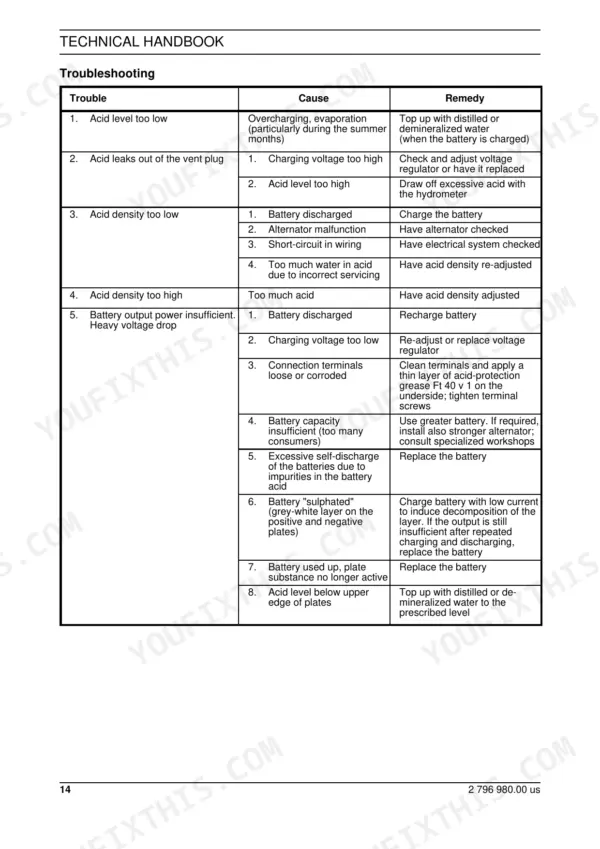
| Electrical System | 348-465 | Electrical Components, Fundamentals of Electrical Engineering (Battery, Alternator, Motors, Circuits), Interpretation of Wiring Diagrams, Troubleshooting, Fuses, Schematic Symbols |
| Frame | 466-471 | Safety Instructions, Repairing Loader Frame, Exchanging Main Pivot Parts, Articulated Joint Assembly |
| Fittings, Pipes and Hoses | 472-521 | Safety Instructions, Materials for Pipes and Hoses, Line System Conditions, Steel Pipes (Cutting, Bending), Hoses (Fitting, Routing) |
| Sealing, Protective, Testing and Cleaning Agents | 522-541 | Safety Instructions, Preservation (Gearboxes, Piston Rods), Corrosion Protection (Pins, Bearings), Sealing Agents (Surface, Thread), Adhesives (Metal, Plastics, O-Rings) |
Quick Reference Specifications
| Specification | Value | Page |
|---|---|---|
| Engine - repair instructions | 10 | p. 3 |
| Working hydraulic | 08 | p. 336 |
| Hydraulic cylinder lifting times (bucket empty) lifting | 6,3 Sec. | p. 61 |
| Cooling system capacity | 18.5 (5) litres (gal) | p. 66 |
| acid-protection grease | Ft 40 v 1 | p. 63 |
| Battery plus | B + | p. 391 |
| Permissible tolerances for hose length alteration under high pressure | -4% to +2% | p. 487 |
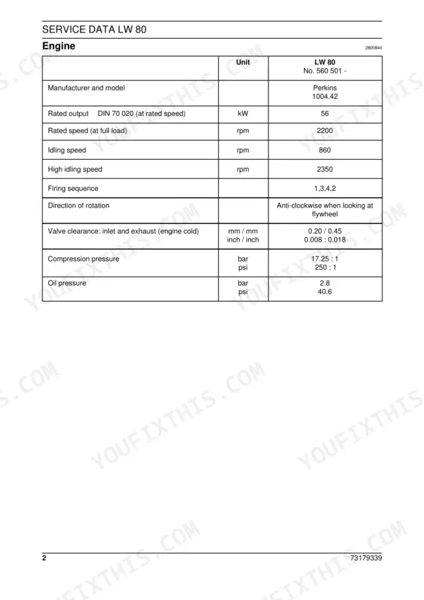
| Engine Rated Output | 56 kW | p. 59 |
| Engine Rated Speed | 2200 rpm | p. 59 |
| Engine Oil Pressure | 2.8 bar | p. 59 |