
Part of the New Holland Repair Manuals.
Looking for a New Holland D150 repair manual PDF you can trust? All 376 pages of this factory book (OEM #604.13.517.00) cover the D150 crawler dozer in every configuration: STD PAT PS, STD BD PS, XLT PAT PS, and LGP PAT PS. You get full hydraulic schematics for the dozer equipment circuit, wiring diagrams for the electrical system, and page after page of tightening torques. Open to the transmission section for torque converter, speed clutch, and modulating valve rebuilds, then hit the undercarriage pages for track chain tension and roller work. Torque the front bearing stop screws to 4.1 to 4.9 daNm (30.24 to 36.14 ft lb), and top the rollers and track chains with 4 L of oil. A dozer parked in the dirt earns nothing. Bookmarked and keyword-searchable; open it on any device and start wrenching.
What's Inside This New Holland D150 Repair Manual
| System | Pages | Key Topics |
|---|---|---|
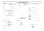
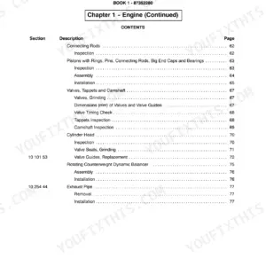
| Summary | 4-5 | Generalities, Engine, Transmission, Final Drives, Brakes and Steering Differential, Undercarriage, Dozer Equipment Hydraulic System, Electrical System |
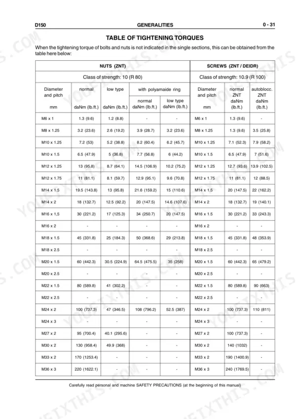
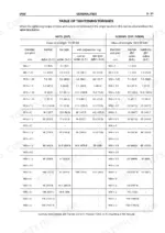
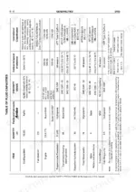
| Sect. 0 Generalities | 6-49 | Safety Rules, Identification Data, Fluid Capacities, Centre of Gravity, Main Dimensions and Weights, Technical Data, Tightening Torques |
| Sect. 1 Engine | 50-61 | Engine Specifications, Engine Identification, Design Features, Serviceability, Securing Engine to Frame |
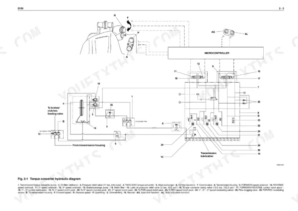
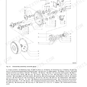
| Sect. 2 Transmission | 62-131 | Torque Converter, Transmission, Transmission Gearshifting Electric Control Valve, Forward Speed Clutch, Reverse Speed Clutch, Modulating Valves, Pressure Relief Valve |
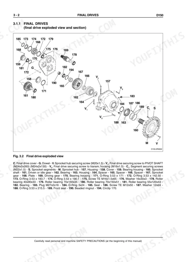
| Sect. 3 Final Drives | 132-155 | Final Drive Removal, Housing Cover, Driven Gear, Driving Gear Shaft, Front Seals, Final Drive Assembly |
| Sect. 4 Brakes and Steering Differential | 156-257 | Brakes Hydraulic Diagram, Steering Hydraulic System, Brake Pedal Valve, Brake Power Pump, Steering Side Group, Bevel Gear Set, Brake Pack |
| Sect. 5 Undercarriage | 258-291 | Track Chain Tension, Track Chains, Idler, Track Chain Support Rollers, Track Chain Bottom Rollers, Track Tensioner Device |
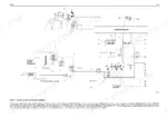
| Sect. 6 Dozer Equipment Hydraulic System | 292-321 | Hydraulic Circuit, Quick Drop Valves, Blade Hydraulic Tilt, Hydraulic Control Valve, Power Hydraulic Pump, Pilot Valve Power Block, Blade Lifting Cylinder, Blade Tilt Cylinder |
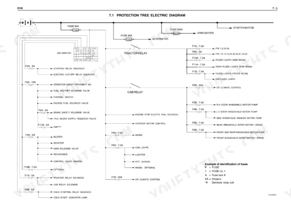
| Sect. 7 Electrical System | 322-350 | Fuses, Main Switch, Engine Starting Switch, Back-Up Alarm, Starter Motor, Instrument Panel, Monitor Senders, Display |
| Sect. 8 Air Conditioning Unit | 351-376 | Heater Group, Conditioner Group, Compressor, Condenser, Thermostatic Valve, Expansion Valve, Dehydrating Filter, Pressure Switch |
Quick Reference Specifications
| Specification | Value | Page |
|---|---|---|
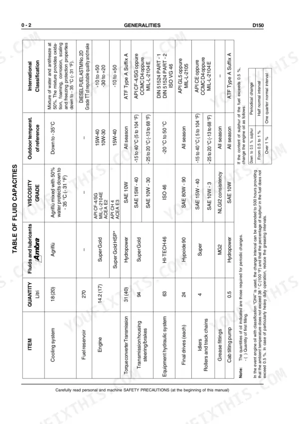
| Rollers and track chains oil quantity | 4 L | p. 19 |
| Batteries - std | 2 x 12 Volt - 100 Amph | p. 26 |
| Batteries - oversized | 2 x 12 Volt - 160 Amph | p. 26 |
| Securing screws, front bearing stop | 4.1 to 4.9 daNm (30.24 to 36.14 ft lb) | p. 120 |
| Securing screws, shaft hub stop | 4.1 to 4.9 daNm (30.24 to 36.14 ft lb) | p. 120 |
| dual bearing (162) warm-up temperature | 110 °C (230 °F) | p. 145 |
| Track chain sag | 30 to 40 mm (1.181 to 1.574 in) | p. 265 |
| Pressure relief valve setting V1 | 6.41 to 6.86 daNm (47.273 to 50.592 ft lb) | p. 266 |
| Pressure relief valve setting V2 | 6.86 to 7.35 daNm (50.592 to 54.206 ft lb) | p. 266 |
| Fuse Box A - 1 | 5 Amp | p. 326 |
| Fuse Box A - 2 | 10 Amp | p. 326 |
| Engine maximum torque | 650 Nm | p. 26 |
New Holland D150 Common Problems This Manual Covers
New Holland D150 engine loses power under load, stalls, and cranks hard after fuel filter change
Replace the fuel filter and bleed the fuel system before chasing bigger problems; contaminated fuel and air in the lines cause most power loss on this machine. After bleeding, start the engine and confirm low idle settles at 850 rpm. If it still stumbles under load, work through the engine service steps starting on page 50.
Manual Section: Sect. 1 Engine p. 50Engine overheats and coolant temperature warning light comes on during heavy pushing in hot weather
Check coolant level cold and blow out the radiator core from the engine side; packed fins cause most overheating on dozers working in dust. Verify fan belt tension and the cap seal. If the warning stays on with a cool engine, suspect the max temperature switch; replace it and torque to 2.5 daNm (18.4 ft lb) per page 337.
Manual Section: Sect. 7 Electrical System p. 337Transmission oil overheats, direction changes feel sluggish, low clutch pressure warning shows on the display
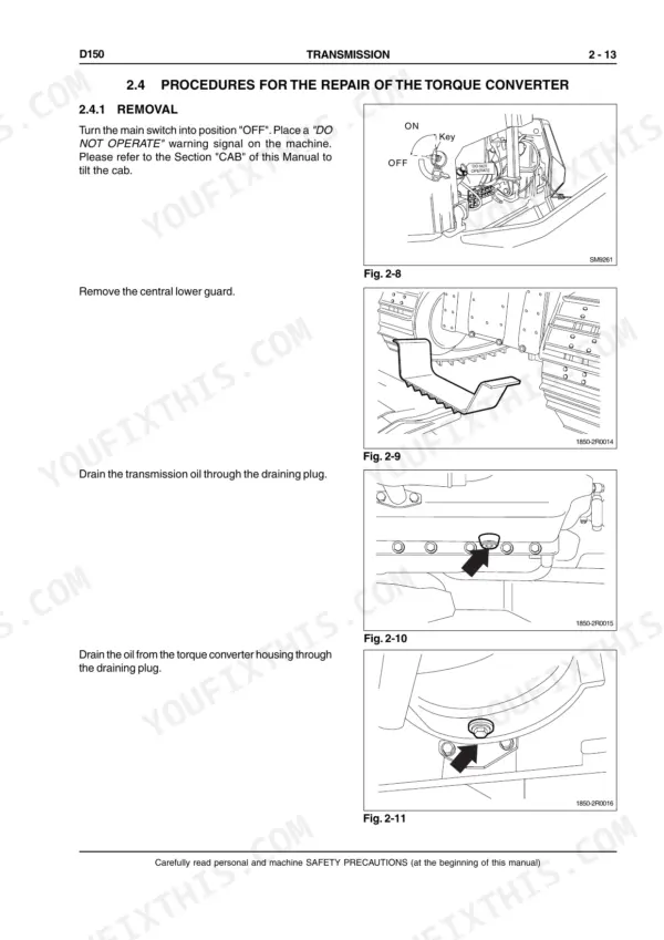
Check transmission oil level hot before pulling anything apart; low oil explains both overheating and slow shifts. Replace the delivery line oil filter and torque it to 4 daNm (29.5 ft lb) as shown on page 129. If a low pressure warning persists, replace the transmission oil low pressure sensor and torque it to 3.5 daNm (25.8 ft lb).
Manual Section: Sect. 2 Transmission p. 129Tracks run slack or over-tight, chain jumps the sprocket, undercarriage parts wearing fast
Measure track sag between the carrier roller and idler; you want 30 to 40 mm (1.181 to 1.574 in) per page 265. Adjust at the tensioner, never past spec; the relief valve opens at 900 to 950 bar. Retorque loose track screws to page 268: master link screws with their shoes take C = 21 to 30 daNm plus a further 180 degrees, and the screws securing them take C1 = 46 to 54 daNm plus a further 120 degrees.
Manual Section: Sect. 5 Undercarriage p. 265Starter clicks but engine won't crank, dash gauges dead, fuses blow intermittently in damp weather
Test both batteries first; this machine runs two 12 volt 100 amp hour batteries, and one weak cell kills cold cranking. Load test them, then clean and tighten the ground straps and starter connections. Check the 80 Amp alternator link fuse and 200 Amp cold starting mega fuse shown on page 327 before condemning the starter.
Manual Section: Sect. 7 Electrical System p. 327Frequently Asked Questions
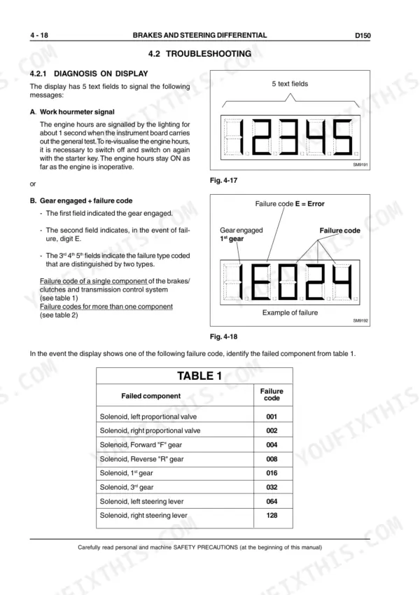
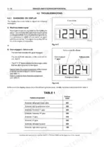
What is the error code for a solenoid failure on the left proportional valve?
The failure code for a solenoid failure on the left proportional valve is 001. This code is identified in Table 1 on page 175 of the manual. p. 175
What is the replacement interval for the transmission oil filter?
The transmission oil filter on the delivery line should be replaced every 500 hours of work. p. 129
What is the correct torque for the final drive housing cover screws?
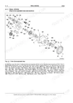
The screws securing the final drive cover should be tightened to a torque of 12 daNm. p. 150
What is the specified clearance between intake valves and rocker arms?
The clearance between intake valves and rocker arms is 0.25 mm (0.009 in). p. 52
What is the capacity of the cooling system?
The cooling system has a capacity of 9.8 litres (2.6 gal.). p. 52
How is this New Holland D150 Repair Manual delivered?
Immediate download of the complete 376-page searchable Repair Manual. Access it on any device, from a laptop at your desk to a phone in the field.
Is this New Holland D150 manual print-friendly?
Yes. Print a single page or a chapter for your own shop use, on letter or A4.




Reviews
There are no reviews yet.