


Part of the New Holland Repair Manuals.
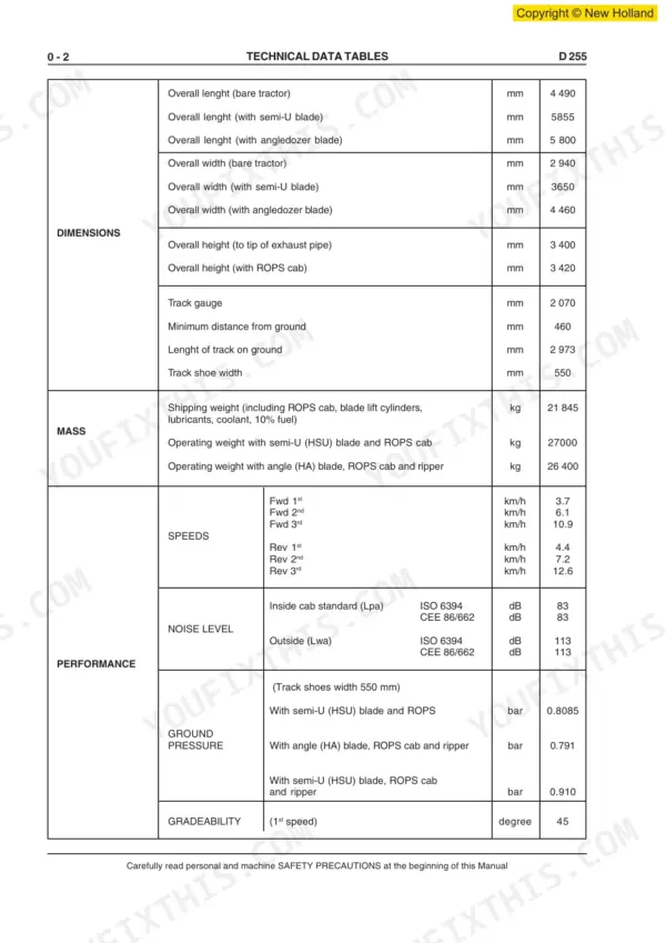
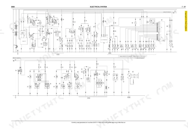
This 337-page New Holland D255 Workshop Manual (OEM #604.13.527.00) covers every system on your D255 Crawler Dozer, from the torque converter transmission down to the final drives. You get wiring diagrams for the electrical system, hydraulic schematics for the dozer blade circuit, and a full troubleshooting section for the steering clutches and brakes. Open to the undercarriage chapter and you get complete track chain, idler, and roller specs alongside the dozer equipment hydraulic pump and control valve breakdown. Torque the master link to 27-39 daNm plus an additional 180 degrees of rotation, and set the hydraulic relief valve between 980 and 1030 bar before you button the machine back up. No more flipping through three different sub-manuals hunting for one torque spec. This PDF carries bookmarks for every section, so you jump straight from the cover to Air Conditioning without scrolling, right from your phone in the shop.
What's Inside This New Holland D255 Manual
| System | Pages | Key Topics |
|---|---|---|
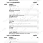
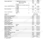
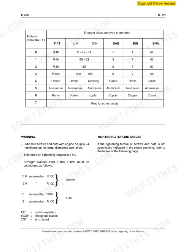
| Generalities | 5-40 | Safety Rules, Technical Data Tables, Diagnostic Checks, Measure Units, Classification of Standard Parts, Tightening Torques |
| Engine | 41-54 | General Specifications, Diagrams of Series "C" Engine |
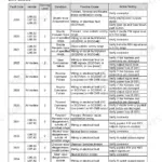
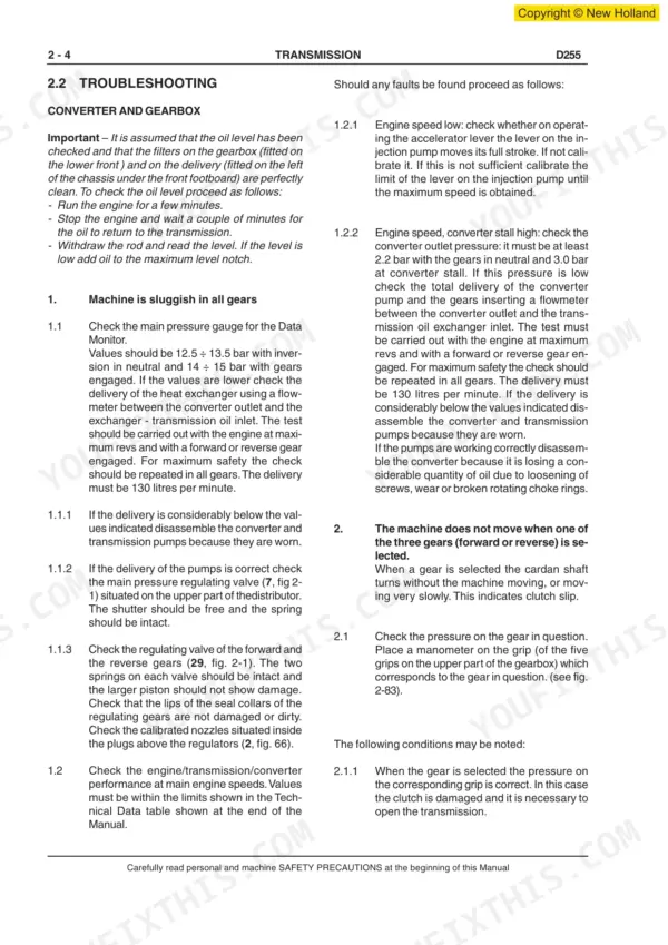
| Transmission-Torque Converter | 55-130 | Troubleshooting, Converter, Gearbox, Transmission Distributor, Control Lever, Testing Transmission/Converter on the Vehicle, Technical Data, Tightening Torques |
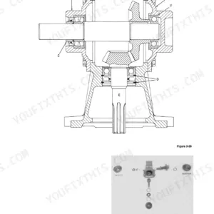
| Steering Clutches - Brakes | 131-191 | General Description, Troubleshooting of Major Malfunctions, Central Reduction Bevel Gear Set, Steering Clutches and Brakes, Steering Clutches and Brakes Control Valve |
| Final Drives | 192-211 | Removal, Disassembly |
| Undercarriage | 212-247 | Track Chains, Track Release and Adjuster Mechanism, Track Idler Wheels, Track Rollers, Track Frames, Specifications and Data |
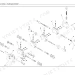
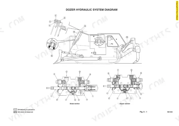
| Dozer Equipment Hydraulic System | 248-283 | Hydraulic Pump, Distributor, Blade Raising and Lowering Control Cylinders, Technical Data |
| Electrical System | 284-313 | Fuses, Electrical System Master Switch, Starter Motor, Alternator, E.D.M. Control Module, Wiring Diagram |
| Air Conditioning Unit | 314-337 | Service Precautions, Leak Inspection, Troubleshooting |
Quick Reference Specifications
| Specification | Value | Page |
|---|---|---|
| TIGHTENING TORQUES | 23 | p. 5 |
| DIAGNOSTIC CHECKS | 21 | p. 5 |
| tightening torque of master link | 27 ÷ 39 daNm plus a further tightening of 180° | p. 244 |
| Relief valve pressure setting | 980 ÷ 1030 bar | p. 241 |
| Engine Total Displacement | 8268 cm3 | p. 19 |
| Engine Oil Total Capacity | 23.8 litres | p. 45 |
| Cooling System Capacity | 9 litres | p. 46 |
| Fuel Tank Capacity | 495 Liter | p. 26 |
| Main Hydraulic Pump Relief Valve Pressure | 190 bar | p. 22 |
| Transmission Pressure (at 66 l/min flow) | 17.0 bar | p. 28 |
| Steering Clutch N. of Friction Discs | 11 | p. 20 |
| Track Shoe Width | 550 mm | p. 18 |