
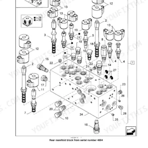
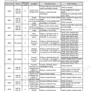
Part of the New Holland Repair Manuals.
C245 fault codes print as plain numbers like 1002 or 1004, and engine controller codes carry their DTC too, such as 3436 (DTC FBBF). Each one gets a context, failure modes and a step-by-step solution that begins with the Electronic Service Tool (EST). The book also covers the hydrostatic drive, main control valve, ride control, tracks, HVAC and the full electrical and hydraulic schematics.
This is New Holland manual 48174793 for the C245 Tier 4B (final) 200 Series, PIN NHM435463 and above. Where mechanical and Electro-Hydraulic (EH) specs differ, the book gives them separately. Engine internal overhaul is not in it. That is in a separate engine manual.
A track loader that won't lift a full bucket while the truck waits makes for a long day. Print the pages you need, take them to the bench and let them get greasy.
What's Inside This New Holland C245 Tier 4B Manual
| System | Pages | Key Topics |
|---|---|---|
| Introduction and General Specifications | 1-35 | Safety Rules, Minimum Tightening Torques and Standard Torque Data for Hydraulics, Hydraulic Contamination, Fluids and Lubricants, Recommended Engine and Hydraulic Oils, General Specification, Product Identification |
| Engine Removal and Installation, Fuel Tank and Filters | 36-89 | Engine and Crankcase Oil Drain, Engine Remove and Install, Engine Filling, Fuel Tanks, Fuel Filters |
| Selective Catalytic Reduction (SCR) Exhaust Treatment | 90-123 | DEF/AdBlue Instrumentation Warnings and Inducement Displays, DEF Crystallization Service Instruction, SCR Muffler and Catalyst Remove and Install |
| Engine Cooling, Fan Drive, Aftercooler and Lubrication | 124-160 | Engine Cooling System, Fan and Drive, Belt Tension Adjust, Aftercooler, Engine Lubrication System and Recommended Engine Oil |
| Power Coupling | 161-168 | Pump-Drive Assembly and Pump-Drive Coupling Torque |
| Hydrostatic Drive | 169-294 | Mechanical Control Adjust, Hydrostatic Pump and Motor General Specifications (Mechanical, Electro-Hydraulic, Enhanced High-Flow), Charge Pressure Relief Valve Pressure Test, Hydrostatic Transmission Troubleshooting |
| Parking Brake | 295-304 | Parking Brake Control Valve General Specification, Motor Valves Remove and Install |
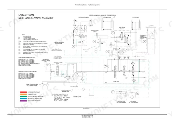
| Hydraulic Schematics, Tests and Reservoir | 305-369 | Component Localization, Hydraulic Schematic Frames 01-04, Pump Efficiency, Circuit Leakage and Relief Valve Pressure Tests, Reservoir, Cooler and Filters |
| Gear Pump and Main Control Valve | 370-425 | Fixed Displacement Pump Specification and Flow Tests, Main Control Valve Specifications, Circuit Leakage Test, Main Relief Valve Pressure Test |
| Auxiliary, High Flow and Loader Hydraulic Controls | 426-493 | Auxiliary Hydraulic Valves and Lines, High Flow Hydraulic Pump and Pilot Valve, Loader Bucket Self-Leveling Controls, Front Loader Bucket Hydraulic System |
| Loader Arm Hydraulics, Ride Control and Quick Coupler | 494-558 | Loader Arm Override and Relief Valves, Ride Control Solenoid Valve Block, Accumulator Charging, Lift Arm Cylinders, Loader Arm Troubleshooting, Tool Quick Coupler Hydraulics |
| Frames, Ballast and Tracks | 559-612 | Ballasts and Supports, Track Frame and Driving Wheels, Rubber Track Remove, Install and Tension Adjust, Track Tension Units, Track Rollers |
| Heating and Air Conditioning | 613-674 | Heating, Air Conditioning Components, Refrigerant Service, Compressor Drive Belt, Air Conditioning Troubleshooting |
| Electrical System Tests and EST Calibrations | 675-703 | Electronic Service Tool Overview, Open Circuit, Short to Ground and Short to Voltage Tests, H1 Calibration Procedures, Diode, Relay and Wire Testing |
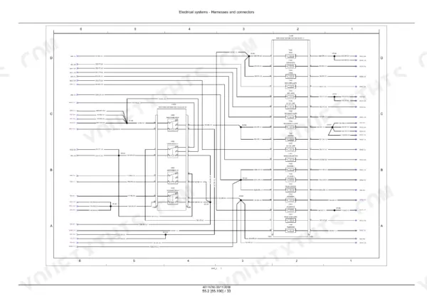
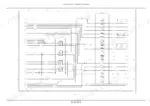
| Electrical Schematics | 704-877 | Harnesses and Connectors Overview, Electrical Schematic Sheets for Power Distribution, Ignition and Charging, Grounding, Engine, Throttle Sensors, Hydraulics, Cab Console and Control Handles |
| Harness Component Localization and Connector Diagrams | 878-1417 | Cab and Chassis Harness Component Localization (Mechanical and Electro-Hydraulic Drive, Open and Closed Cab), Connector Component Diagrams |
| Starting, Charging and Electronic Controls | 1418-1635 | Cab Engine Controls, Engine Starting System Troubleshooting, Alternator, Battery, Fuel Tank System, SCR Electrical System, Engine Cooling System Electrical, Electronic Modules, Hydrostatic Drive Control, Cab Controls, Hydraulic System Control, HVAC Control, Wipers, Warning Indicators, Telematics |
| Fault Codes: Cluster, VCM and Engine Controller | 1636-2003 | Fault Code Index; Diagnostic Procedures for Instrument Cluster and VCM Codes Such As 1002 and Engine Controller Codes Printed with Their DTC, Such As 3436 (DTC FBBF) |
| Fault Codes: Hydraulic, Loader and DEF/AdBlue | 2004-2644 | Diagnostic Procedures for Hydraulic Sensor, Loader Pilot Interlock, Memory and DEF/AdBlue Supply Module Codes, From 4043 to 19748 |
| Front Loader and Bucket | 2645-2696 | Loader Arm and Bucket |
| Platform, Cab and Bodywork | 2697-2761 | Cab Interior Trim, Mechanically and Pneumatically Adjusted Operator Seats, Cab, Cab Doors and Hatches, Engine Shields and Hood Latches |
| Special Tool Index and Fold-Out Schematics | 2762-2784 | Special Tool Index, Electrical Schematic Electro-Hydraulic (EH) Controls 51570587, Electrical Schematic Mechanical Controls 51570588, Hydraulic Schematic 51570580 |
Quick Reference Specifications
| Specification | Value | Page |
|---|---|---|
| Engine | F5BFL413A*B007 | p. 3 |
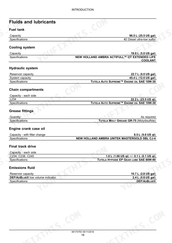
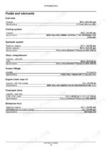
| Fuel tank | 96.5 L (25.5 US gal), #2 Diesel ultra-low sulfur | p. 25 |
| Cooling system | 19.0 L (5.0 US gal), NEW HOLLAND AMBRA ACTIFULL OT EXTENDED LIFE COOLANT | p. 25 |
| Hydraulic reservoir | 22.7 L (6.0 US gal) | p. 25 |
| Hydraulic system | 45.4 L (12.0 US gal), TUTELA AUTO SUPREME ENGINE OIL SAE 10W-30 | p. 25 |
| Engine crank case oil (with filter change) | 8.5 L (9.0 US qt), NEW HOLLAND AMBRA UNITEK MASTERGOLD SBL CJ-4 | p. 25 |
| Final track drive (each side) | 1.0 L (1.06 US qt) +/- 0.1 L (0.1 US qt), TUTELA HYPOIDE EP GEAR LUBE SAE 80W-90 | p. 25 |
| DEF/AdBlue reservoir | 10.7 L (2.8 US gal) | p. 25 |
| Engine oil maximum service change interval | 600 h | p. 26 |
| Hydrostatic pump displacement | 46 cm³ (2.8 in³) Sauer-Danfoss (Mechanical drive) / 45 cm³ (3 in³) Bosch Rexroth (Electro-Hydraulic (EH) drive) | p. 181 |
| Charge pressure relief valve | 24 - 25 bar (350 - 370 psi) at 1800 RPM (Mechanical drive) / 24 - 26 bar (347 - 377 psi) (Electro-Hydraulic (EH) drive) | p. 181 |
| Pressure limiter valves | 360 - 378 bar (5220 - 5481 psi) (Mechanical drive) / 350 - 370 bar (5075 - 5365 psi) (Electro-Hydraulic (EH) drive) | p. 181 |
| Charge pressure test reading (high idle) | approximately 24 bar (350 psi) | p. 195 |
| Gear pump | 36.6 cm³ (2.23 in³), 92.3 l/min (24.4 US gpm) | p. 372 |
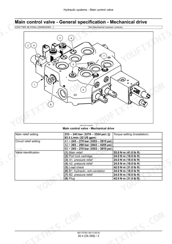
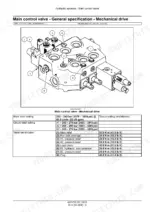
| Main relief setting | 233 - 243 bar (3379 - 3524 psi) @ 83.3 L/min (22 US gpm) | p. 388 |
| Main relief cartridge torque | 55.0 N·m (41.0 lb ft) | p. 388 |
| High flow pilot valve relief setting | 224.0 bar (3250.0 psi) | p. 351 |
| Rubber track tension (center rollers to track) | 12 - 19 mm (7/16 - 3/4 in) | p. 584 |
| Pump-drive coupling flange bolt | 23 - 31 N·m (204 - 274 lb in), LOCTITE 243 | p. 164 |
New Holland C245 Tier 4B Common Problems This Manual Covers
Machine steers off a straight line
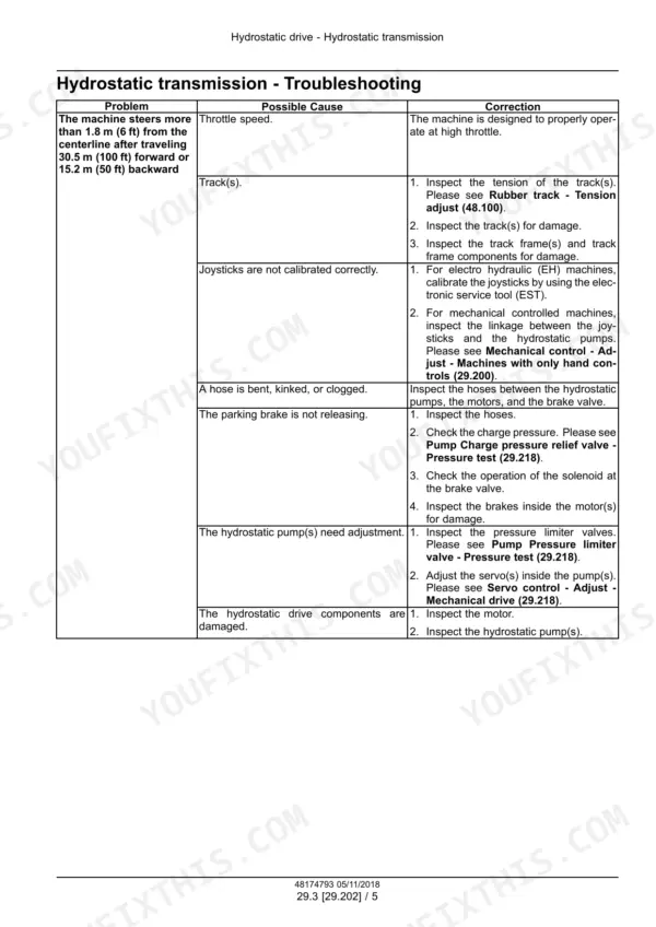
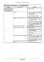
The chart on page 290 counts it as a fault if the machine drifts more than 1.8 m (6 ft) off centerline after 30.5 m (100 ft) forward or 15.2 m (50 ft) backward. Listed causes include throttle speed, the tracks, joystick calibration (EST on EH machines, pump linkage on mechanical ones), a bent, kinked or clogged hose, and a parking brake that is not releasing.
Manual Section: Hydrostatic drive p. 290Hydraulic filter restriction warning
Code 1004 on page 1653 explains that an open circuit on restriction input X-C23 (Male) pin 2 means the filter is restricted. The listed failure modes include a clogged hydraulic filter, an open signal wire, a faulty switch reading and a faulty instrument cluster. Step 2 has you inspect the hydraulic filter and replace it if needed.
Manual Section: Fault codes: cluster, VCM and engine controller p. 1653Engine derate with DEF/SCR warnings
Pages 92-93 explain each display. dEF + LEVEL means DEF is below 10% of tank volume, with no power loss and a one second alarm every 3 min. dEF + EMPTY means below 5%, with torque and engine speed reduction and a continuous alarm. SCR + FAIL escalates at 60 min and 4 h. The book says to troubleshoot it with the EST.
Manual Section: Selective Catalytic Reduction (SCR) exhaust treatment p. 92Loader arm drift or loader will not raise
Page 540 lists causes in this order: the OPERATE button, seat belt, seat switch, override valve, cab door or door switch, and joystick calibration or linkage. Next come the pilot interlock or port lock solenoid, low hydraulic pressure, the main control valve, damaged linkage, the main relief valve and the gear pump. For drift complaints, page 504 says the ride control valve MUST be capped off to isolate the ride control components.
Manual Section: Loader arm hydraulics, ride control and quick coupler p. 540Frequently Asked Questions
How do I read or clear fault codes on a New Holland C245?
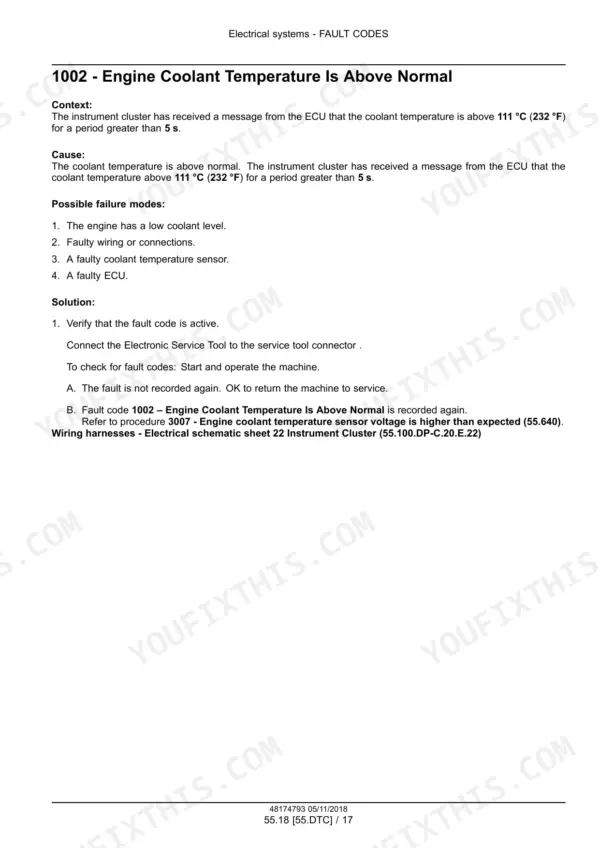
Each code procedure in the fault code sections is built around the Electronic Service Tool (EST). For code 1002, step 1 is to connect the EST and verify the fault code is active. Each procedure then lists the possible failure modes and a step-by-step solution. You work through them until you find the cause. The fault code index opens the section on page 1636, and the procedures run in numeric order, from code 1002 on page 1652 to 19883 on page 2628. p. 1652
What does error code 1002 mean on a C245?
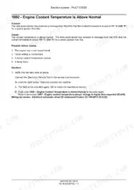
1002 is Engine Coolant Temperature Is Above Normal. The instrument cluster has had a message from the ECU that coolant has been above 111 C (232 F) for more than 5 s. The book lists four possible failure modes: low coolant level, faulty wiring or connections, a faulty coolant temperature sensor and a faulty ECU. The procedure is on page 1652. p. 1652
Where are the torque specs for the C245?
Standard torque data for hydraulics is in the introduction section (pages 1-35). The main control valve table on page 388 is for mechanical drive machines. It lists main relief at 55.0 N·m (41.0 lb ft). The port lock cartridge, A1/A2/B2 reliefs and B1 anti-cavitation valve are 24.0 N·m (18.0 lb ft). The load check and plug are 42.0 N·m (31.0 lb ft). The pump-drive coupling flange bolt is 23 - 31 N·m (204 - 274 lb in) with LOCTITE 243 (page 164). p. 388
What should C245 charge pressure read?
Mechanical drive machines use a Sauer-Danfoss pump with a charge relief of 24 - 25 bar (350 - 370 psi) at 1800 RPM (page 181). EH machines use a Bosch Rexroth pump rated 24 - 26 bar (347 - 377 psi) (page 183). For the test, warm the hydraulic oil to at least 52 C (125 F). Fit a 41 bar (600 psi) gauge, part number 380500129, to the test port or to a T-fitting in the charge pump outlet hose. At high idle it should read about 24 bar (350 psi) (pages 194-195). p. 195
What are the C245 fluid capacities and oil types?
The fuel tank holds 96.5 L (25.5 US gal) and the cooling system 19.0 L (5.0 US gal). The hydraulic system takes 45.4 L (12.0 US gal) of TUTELA AUTO SUPREME ENGINE OIL SAE 10W-30. The crankcase takes 8.5 L (9.0 US qt) with a filter change. Each final track drive holds 1.0 L (1.06 US qt) +/- 0.1 L (0.1 US qt) of SAE 80W-90. The DEF/AdBlue reservoir holds 10.7 L (2.8 US gal) (page 25). The maximum engine oil change interval is 600 h (page 26). p. 25






Reviews
There are no reviews yet.