

Part of the New Holland Repair Manuals.
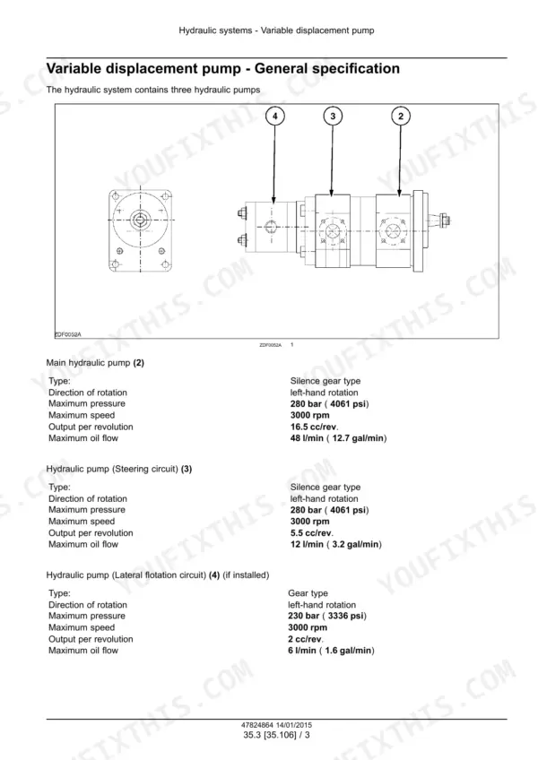
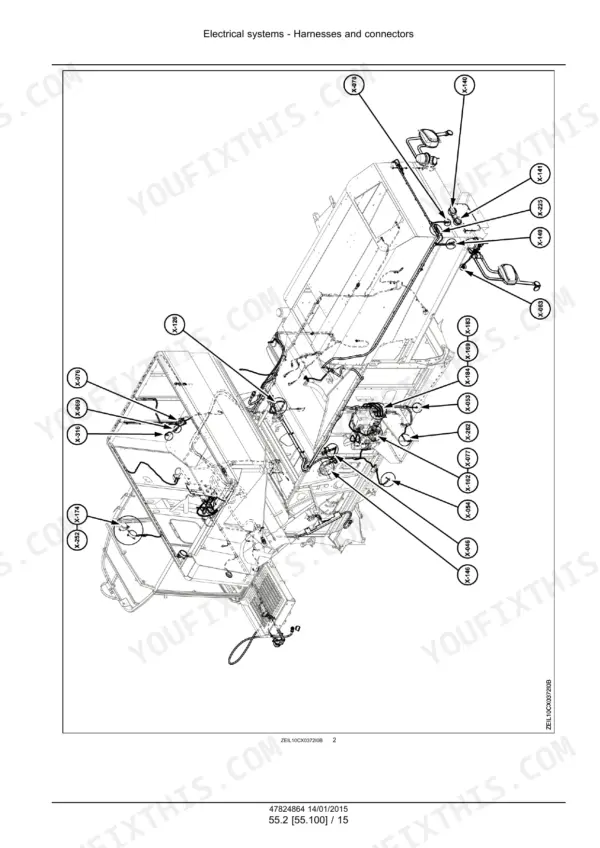
This is the factory service manual for the New Holland CX5080, CX5090, CX6080 and CX6090 combines, covering the Elevation, Laterale and Hillside builds (publication 47824864, issued January 2015). It works the whole machine: engine, main gearbox, transmission, front and rear axles, hydrostatic drive, brakes, hydraulics, steering, cab climate and electrical systems, then the harvesting side - headers, product feeding, threshing, separation, cleaning, grain tank and unloading. You get the full hydraulic schema on p488, real pump test values (main pump 280 bar, 48 l/min, 16.5 cc/rev on p506), a large fault code index starting p1424 with diagnostic and CAN bus test procedures, harness routing drawings, connector views and a special tool index. Written for the mechanic doing the work, not the showroom.
What's Inside This New Holland CX5080–CX6090 Series Manual
| System | Pages | Key Topics |
|---|---|---|
| Contents | 4-8 | Section Contents, Manual Organisation |
| Introduction | 9-30 | Machine Identification, Standard Torque Data, Consumables |
| Engine | 31-102 | Engine Service, Air Compressor, Removal and Overhaul |
| Main Gearbox and Drive | 103-140 | Main Gearbox, Drive Components |
| Transmission | 141-246 | Mechanical Transmission, Torque Values, Component Weights |
| Front Axle System | 247-302 | Front Axle, Final Drives |
| Rear Axle System | 303-326 | Rear Axle, Steering Axle Service |
| Hydrostatic Drive | 327-444 | Hydrostatic Pump and Motor, Drive Control |
| Brakes and Controls | 445-480 | Hydraulic Service Brakes, Brake Disks, Controls |
| Hydraulic Systems | 481-618 | Hydraulic Schema, Variable Displacement Pump, Main Control Valve, Machine Leveling Control |
| Steering | 619-674 | Power Steering Control Valve, Autoguidance Steering, Hydraulic Control Components |
| Cab Climate Control | 675-730 | Heating, Ventilation, Air Conditioning |
| Electrical Systems, Harnesses and Connectors | 731-1389 | Electrical Symbols, Component to Schematic Sheet Index, Harness Routing Drawings, Connector Views, Special Tools |
| Fault Code Index, Dcu and CM1 to CM2 Codes | 1390-1767 | SCR Electrical System, Dosing Control Unit Codes, CM1 and CM2 Fault Codes, Diagnostic Procedures |
| Fault Code Index, CM3, Handle, Drive and Engine Control | 1768-2399 | CM3 Fault Codes, Multi Function Handle Codes, Drive Unlock Codes, Engine Control Codes |
| CAN Bus Tests, Modules and Machine Electrics | 2400-2696 | CAN Bus Circuit Tests, Electronic Modules, Hydrostatic Drive Control, Cab HVAC Electrics, External Lighting, Sieve Electric Control, Warning Indicators, Precision Farming, Harvest Material Flow Control |
| Attachments/Headers | 2697-2714 | Header Attachment, Header Controls |
| Product Feeding | 2715-2792 | Feeder, Elevator, Stone Trap |
| Threshing | 2793-2870 | Rotor and Concave, Threshing Adjustment |
| Separation | 2871-2952 | Straw Walkers, Separation Components |
| Cleaning | 2953-3090 | Sieves, Cleaning Fan, Grain Pan |
| Crop Storage / Unloading | 3091-3178 | Grain Tank, Unloading Auger, Storage Components |
| Platform, Cab, Bodywork, and Decals | 3179-3197 | Operator Platform, Cab, Bodywork, Decals |
| Special Tool Index | 3198-3203 | Special Service Tools Index |
Quick Reference Specifications
| Specification | Value | Page |
|---|---|---|
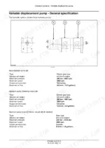
| Main hydraulic pump maximum pressure | 280 bar (4061 psi) | p. 506 |
| Main hydraulic pump maximum oil flow | 48 l/min (12.7 gal/min) | p. 506 |
| Main hydraulic pump output per revolution | 16.5 cc/rev | p. 506 |
| Steering circuit pump output per revolution | 5.5 cc/rev | p. 506 |
| Steering circuit pump maximum oil flow | 12 l/min (3.2 gal/min) | p. 506 |
| Main hydraulic pump maximum speed | 3000 rpm | p. 506 |
New Holland CX5080–CX6090 Series Common Problems This Manual Covers
Combine throws a fault code mid harvest and starts dropping functions
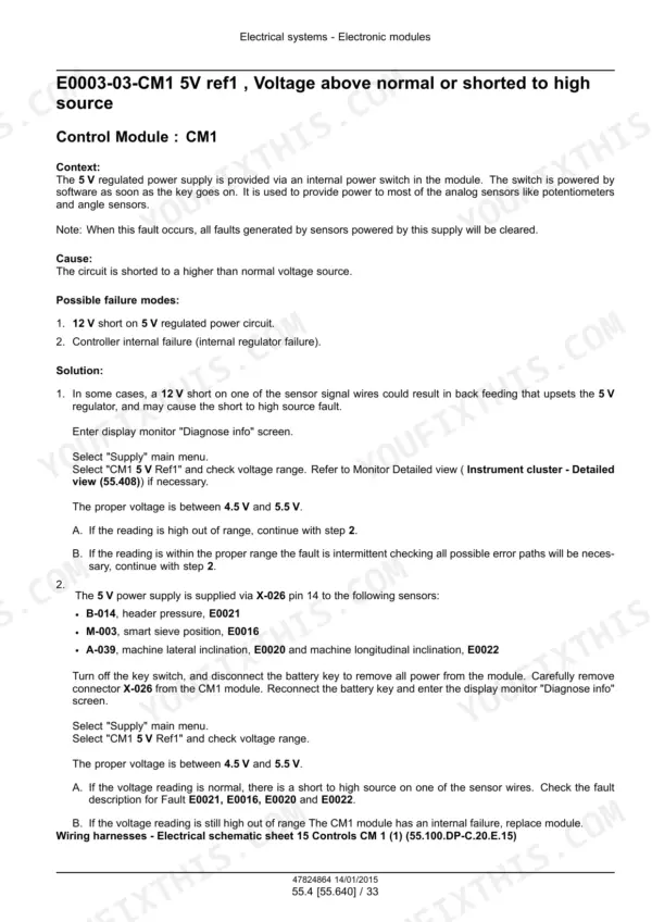
Go straight to the fault code index starting on p1424 in the Electrical systems section. Look up your exact code, follow the diagnostic procedure for that module, and run the CAN bus tests before you condemn any sensor or control unit.
Manual Section: Electrical systems p. 488Header lift is slow or the hydraulics feel weak under load
Put a gauge on it and compare against the Hydraulic systems section values: 210 bar system limit, 207 bar pilot at the main stack valve, 3 bar load sensing delta P. The schema on p488 and pump specs on p506 tell you whether the 48 l/min main pump is delivering or the valve stack is bleeding pressure.
Manual Section: Hydraulic systems p. 1424Laterale flotation hunts or will not level properly on side slopes
The lateral flotation circuit runs its own small gear pump (2 cc/rev, 230 bar max) feeding a stack valve with a 175 bar pilot setting. The Hydraulic systems section gives those test values and the valve procedures, so verify pump delivery and pilot pressure before swapping cylinders or position sensors.
Manual Section: Hydraulic systems p. 2953Hydrostatic drive feels sluggish or loses power on hills
The Hydrostatic drive section walks the drive circuit end to end so you can test before you tear anything down. Rule out the cheap stuff first - oil level, filters - then follow the section's test procedures to separate a worn hydro unit from a control or relief fault.
Manual Section: Hydrostatic drive p. 506Frequently Asked Questions
My display is throwing codes like E0258-04-CM2. Will this manual tell me what they mean?
Yes, and this is one of the book's strong points. The fault code index starts on p1424 and runs codes in exactly that format - E0002-04-CM1, E1283-07-MFH, E1655-12 for engine control and so on - each tied to a diagnostic procedure. It also includes CAN bus test procedures, which matter on these machines because half the 'sensor faults' you chase turn out to be bus or connector problems. p. 488
Are full wiring diagrams included?
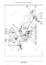
No. The electrical circuit schematic sheets are a separate New Holland document. What this book does carry is the index that names every schematic sheet by component, harness routing drawings showing where each loom physically runs on the machine, and connector views. Between those, the fault code index and the CAN bus tests, you can trace most electrical problems, but if you want the actual circuit sheets, plan on getting the schematic set as well. p. 765
Does it give real test numbers for the hydraulics, or just remove and install steps?
Real numbers. The hydraulic schema is on p488 and pump specs on p506: main pump 280 bar (4061 psi) max at 48 l/min (12.7 gal/min) and 16.5 cc/rev, steering circuit pump 5.5 cc/rev at 12 l/min. You also get working values like the 210 bar system pressure limit, 207 bar pilot at the main stack valve and the 3 bar load sensing delta P, so you can put a gauge on the machine and know what you should be seeing. p. 1424
Does this cover the Laterale and Hillside versions or just the standard combine?
All four models in all three builds: Elevation, Laterale and Hillside. The Laterale's lateral flotation circuit gets its own treatment, including the dedicated gear pump (2 cc/rev, 230 bar max, 6 l/min) and the lateral float stack valve with its 175 bar pilot setting. If you run a leveling machine on slopes, those numbers are what you need when the flotation starts misbehaving. p. 506
Is the harvesting side covered, or mostly engine and driveline?
The whole machine. Headers and attachments, product feeding, threshing, separation, cleaning and crop storage / unloading each have their own section, alongside engine, main gearbox, transmission, axles, hydrostatic drive, brakes, steering, cab climate control and the electrical systems. There is also a special tool index so you know what NH tooling a job calls for before you open the machine up. p. 2793






Reviews
There are no reviews yet.