
Part of the New Holland Repair Manuals.
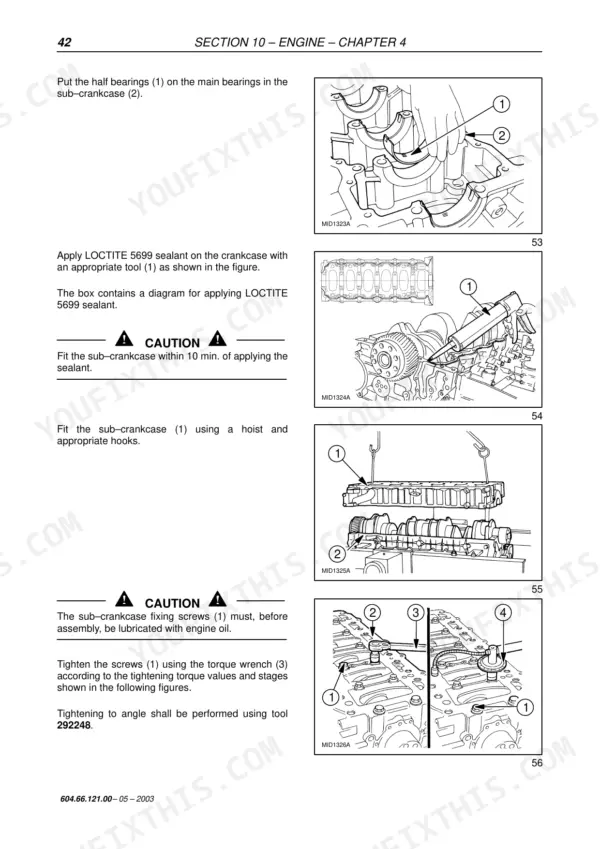
Factory workshop manual (pub. no. 604.66.121.00, May 2003) for the New Holland FX30, FX30NA, FX40, FX40NA, FX50, FX60 and FX60NA self-propelled forage harvesters. This is the book dealer techs used: full teardown and rebuild procedures for the IVECO F3A and F3B engines, traction gearbox and differential with shim calculations, 4WD lines, hydrostatic drive, work and steering hydraulics, brakes, cab air conditioning, and the whole crop path from feed rolls through cutterhead to blower. The electrical chapters cover wiring diagrams, CAN network basics, calibration, software update and error-code troubleshooting. Note on engines: both IVECO units are fully specced and serviced here; the Caterpillar C-15 option is not - Cat engine service goes through the Caterpillar dealer network.
What's Inside This New Holland FX30–FX60 Series Manual
| System | Pages | Key Topics |
|---|---|---|
| General Information | 18-34 | - |
| Engine | 35-322 | IVECO Engine F3A, IVECO Engine F3B, Caterpillar Engine, Disassembly and Assembly, Lubrication, Cooling |
| Transmission | 323-336 | Gearbox Shafts, Traction Gearbox, Differential, Shifting Diagram, Shims Calculation |
| WD Lines | 337-362 | 4WD Gearbox Removal, 4WD Gearbox Assembly, Clutch Cylinder, Input and Output Shafts |
| Front Mechanical Drive | 363-380 | Final Drives FX30, Final Drives FX40-50-60, Wheel Bolt Replacement, End Play and Preload Adjustment |
| Hydrostatic System | 381-402 | Hydrostatic Pump and Motor, Servo Valve, Oil Cooler Bypass Valve, Filling and Bleeding |
| Brakes and Control | 403-412 | Parking Brake Adjustment, Brake Lining Replacement, Bleeding Brake Circuits, Brake Shoes and Discs |
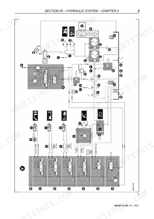
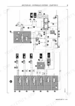
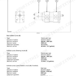
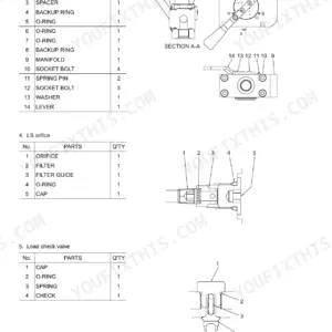
| Hydraulic System | 413-494 | Work Hydraulics, Attachment Height Control, Steering Hydraulics, Low Pressure Hydraulics, High-Flow Hydraulics |
| Cab Climate Control | 495-504 | Air Conditioning Circuit, Compressor Clutch, Ventilation Unit, Refrigerant |
| Electrical System, Fuses and Relays | 505-530 | Fuse Protection, Relays, Electrical Component Identification |
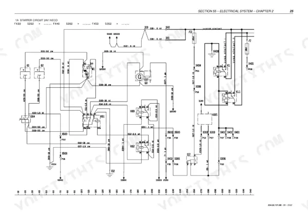
| Electrical System, Wiring Diagrams FX Europe | 531-638 | Starter Circuit 24V IVECO, Engine Throttle Control Caterpillar, Crop Processor, Air Conditioning |
| Electrical System, Symbols and Diagram Legend | 639-738 | List of Symbols and Where to Find Them, Prints and Monitors |
| Electrical System, CAN Network | 739-756 | CAN Network, Electronic System Layout |
| Electrical System, Calibration with EST Tool | 757-792 | Machine Calibration with EST Tool |
| Electrical System, Software Programming | 793-796 | - |
| Electrical System, Troubleshooting | 797-976 | Machine Error Messages, Error Code Descriptions and Explanations |
| Product Feeding | 977-1050 | Feed Rolls, Hydroloc Gearbox, Attachments Drive Gearbox, Upper Feed Rolls Drive Gearbox |
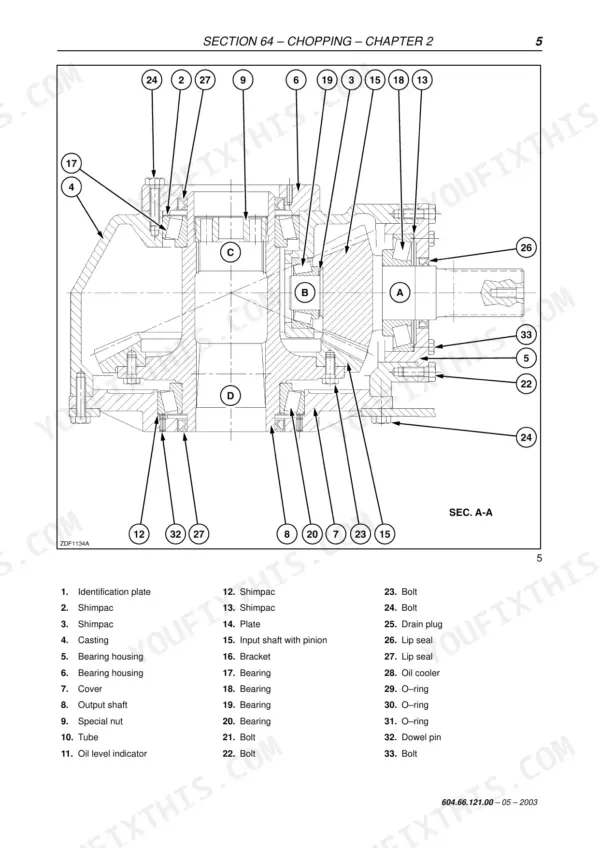
| Chopping | 1051-1072 | Cutterhead, Shearbar, Cutterhead Gearbox |
| Ejection | 1073-1076 | Blower Gearbox, Inspection Between Cutterhead and Blower |
Quick Reference Specifications
| Specification | Value | Page |
|---|---|---|
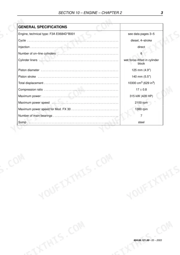
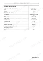
| Engine, technical type | F3A E0684D*B001 | p. 57 |
| Injection | F3A: direct; F3B: direct | p. 57 |
| Number of on-line cylinders | 6 | p. 57 |
| Total displacement | F3A: 10300 cm3 (629 in3); Mod. FX 40: 12880 cm³; Mod. FX 50: 12880 cm³ | p. 57 |
| Compression ratio | F3A: 17 ± 0.8; Mod. FX 40: 16.5 ± 0.8; Mod. FX 50: 16.5 ± 0.8 | p. 57 |
| Maximum power | F3A: 315 kW (428 HP); Mod. FX 40: 315 kW (428 HP); Mod. FX 50: 354 kW (481 HP) | p. 57 |
| Maximum power speed | F3A: 2100 rpm; F3B: 2100 rpm; Mod. FX 40: 1340 rpm; Mod. FX 50: 1340 rpm | p. 57 |
| Piston diameter | F3A: 125 mm (4.9″); Mod. FX 40: 135 mm; Mod. FX 50: 135 mm | p. 57 |
| Piston stroke | F3A: 140 mm (5.5″); Mod. FX 40: 150 mm; Mod. FX 50: 150 mm | p. 57 |
| Number of main bearings | 7 | p. 203 |
| Sump | steel | p. 203 |
| Turbocharger Holset type | HX60W-0988 O/AX 27Z | p. 207 |
| Injectors Bosch type | PDE 31 12 Volt | p. 207 |
| Nozzle Bosch type | DLLA 140 PV3 | p. 207 |
| Electronic injection type | BOSCH EDC MS6.2 | p. 206 |
| Valve-rocker arm clearance (with engine cold) | intake: 0.40 ± 0.05 mm; exhaust: 0.60 ± 0.05 mm | p. 206 |
| Cylinder liners | F3A: wet force-fitted in cylinder block; F3B: wet force-fitted in cylinder block | p. 57 |
| Injection pressure | 1500 bar | p. 207 |
| Injection sequence | 1-4-2-6-3-5 | p. 207 |
New Holland FX30–FX60 Series Common Problems This Manual Covers
Sharpening stone or shearbar adjuster motor fault (error codes 483, 487)
The Electrical System troubleshooting section decodes the fault, then has you check the sharpening stone and shearbar adjuster motors for open or shorted windings, test the supply through the harness and relays, and verify operation after repair.
Manual Section: SECTION 55 - ELECTRICAL SYSTEM - CHAPTER 7 p. 841Cutterhead running slow or no cutterhead-speed reading
The Electrical System sensor list gives the exact mounting location for the cutterhead speed sensor (rear right-hand cutterhead drive pulley) and the shearbar knock sensors, so you confirm sensor position and wiring before assuming a drive fault.
Manual Section: SECTION 55 - ELECTRICAL SYSTEM (Sensors, limit switches, buzzers, speakers) p. 643Frequently Asked Questions
My display shows error 483 or 487 and the knife sharpening cycle will not run. Does this manual cover that?
Yes. Codes 483 (cutterhead cover motor) and 487 (sharpening motor) usually mean the sharpening stone motor or shearbar adjuster motor circuit is open or shorted. The electrical troubleshooting section walks the codes back to the motor, wiring and relay so you test before you buy parts. p. 841
Does this manual cover the Caterpillar engine option?
No, and it says so plainly. The manual prints full service data for the IVECO F3A (10.3 L, 315 kW) and F3B (12.88 L turbo aftercooled) engines only. If your FX has the Caterpillar C-15, New Holland directs you to the Caterpillar dealer network for engine internals. Everything downstream of the flywheel is still covered here. p. 319
What is the engine oil capacity and change interval?
FX30 takes 29 litres, FX40 and FX50 take 35 litres, FX60 takes 34 litres. Change interval is every 600 hours on FX30/40/50 and every 500 hours on FX60, after the first change at 100 hours. The lubrication section lists the approved oil grades alongside. p. 34
The cutterhead runs slow or the monitor shows no cutterhead speed. Where do I start?
Start with the cutterhead speed sensor on the rear right-hand cutterhead drive pulley and the shearbar knock sensors - out-of-position or failed sensors are the usual cause the manual points to before a drive fault. p. 643
Are gearbox rebuild procedures actually in here, with shim and preload figures?
Yes. The transmission chapter covers gearbox shaft disassembly, the traction gearbox, differential and shim calculation for setting backlash. The front mechanical drive chapter has end play and preload adjustment for the final drives, split by FX30 versus FX40/50/60, plus wheel bolt replacement.
What does the blinking self-diagnostic light mean?
The manual explains a blinking-code sequence, but ONLY for the attachment height control system (first blink period = first digit of the error, second period = second digit). It is not a general fault-code guide for the whole machine - treat it as covering attachment-height errors specifically, not every electrical fault. p. 847
Where is the machine's identification/serial plate?
The manual grounds an identification plate on the hydrostatic pump and motor housing (SECTION 29 - HYDROSTATIC SYSTEM) - that is a component ID plate, NOT confirmed as the machine's main chassis/frame serial tag. Do not treat this as the primary machine serial number location without further confirmation. p. 384





Reviews
There are no reviews yet.