Part of the New Holland Repair Manuals.
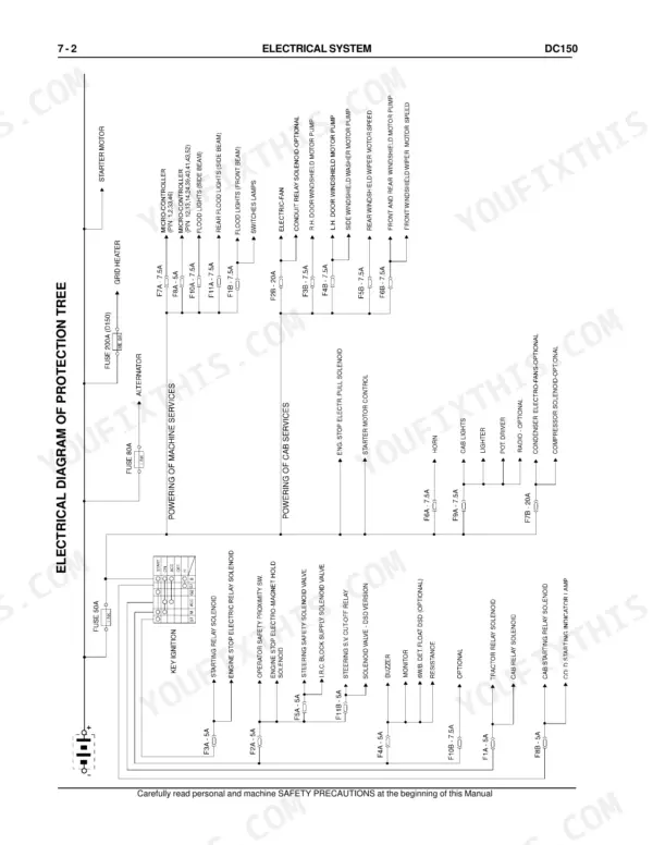
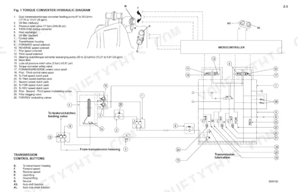
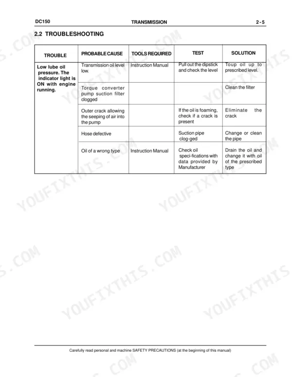
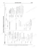
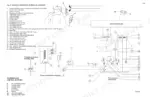
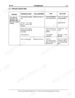
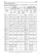
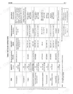
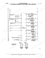
Setting up the track tensioner device, idler and rollers on a New Holland DC150 dozer crawler is one of the jobs set out across the 312 pages of this New Holland DC150 service manual PDF, OEM ID 60402262. Electrical wiring diagrams trace the circuits through the fuses, main switch, engine starting switch, starter motor and instrument panel monitor senders, while hydraulic schematics map oil flow through the transmission and the brake and steering clutch circuits. Troubleshooting guidance starts in Generalities, next to the Table of Tightening Torques. Fit transmission delivery filters rated at 25 micron and steering delivery filters at 30 micron, and keep engine intake restriction within 635 mm (25 in) H2O at rated speed and load. Your job might be the final drives, or the steering clutches and brakes. Each page prints cleanly as a working copy, and bookmarks plus a searchable text layer get you to the right section before you print.
What's Inside This Manual
| System | Pages | Key Topics |
|---|---|---|
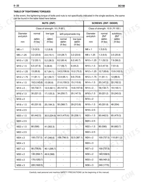
| Generalities | 14-47 | Safety Rules, Table of Technical Data, Troubleshooting, Units of Measure, Classification of Standard Components, Table of Tightening Torques |
| Engine | 48-59 | Series B Engine Specifications, Engine Identification, Design Features, Engine Mounting |
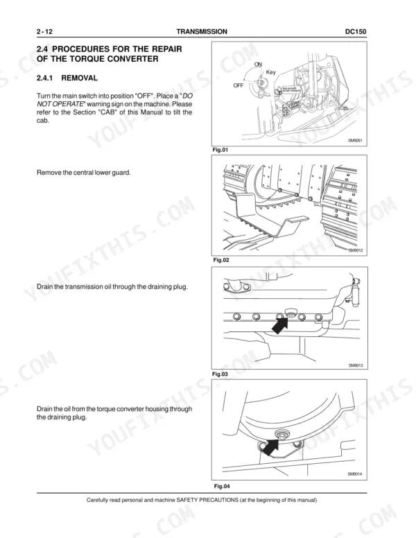
| Transmission | 60-129 | Torque Converter, Transmission Housing, Propeller Shaft, Modulating Valves, Pressure Relief Valve |
| Final Drives | 130-153 | Final Drive, Housing Cover, Driven Gear, Driving Gear Shaft, Front Seals |
| Brakes and Steering Clutches | 154-221 | Feeding Pump, Feeding Valve Block, Proportional Solenoid Valves, Brake Pedal Valve, Bevel Gear Unit |
| Undercarriage | 222-253 | Track Chains, Idler, Support Rollers, Bottom Rollers, Track Tensioner Device, Cross-Member Pivots |
| Dozing Equipment Hydraulic System | 254-288 | Hydraulic Oil Reservoir, Equipment Hydraulic Pump, Hydraulic Control Valve, Blade Lifting Control Cylinder, Ripper Cylinder |
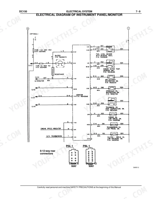
| Electrical System | 289-312 | Fuses, Main Switch, Engine Starting Switch, Starter Motor, Instrument Panel Monitor, Monitor Senders |
Quick Reference Specifications
| Specification | Value | Page |
|---|---|---|
| Steering system filters suction filtering capacity | 100 micron | p. 33 |
| Steering system filters delivery filtering capacity | 30 micron | p. 33 |
| Transmission filters suction filtering capacity | 100 micron | p. 32 |
| Transmission filters delivery filtering capacity | 25 micron | p. 32 |
| Maximum allowable restriction on intake at rated speed and load with clogged cartridge | 635 mm (25 in) H2O | p. 50 |
| Battery | 2 x 12 V - 100 Ah | p. 31 |
| Alternator | 24 V - 70 A | p. 31 |
| Main control valve safety valve setting | 190 bar (2698 psi) | p. 34 |
| Lube pressure at low idle | 0.69 bar (10 psi) | p. 50 |
| Lube pressure at setting speed | 2.07 bar (30 psi) | p. 50 |
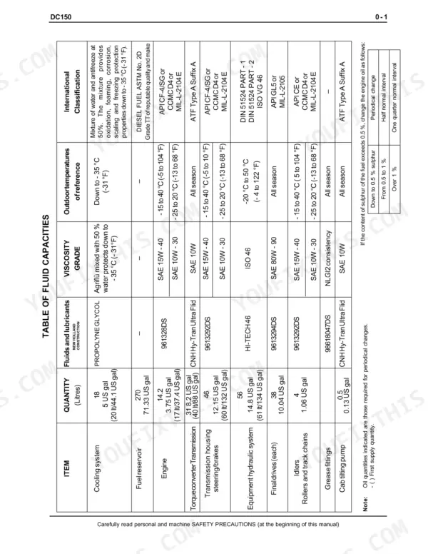
| Quantity of oil to fill final drives | 38 litres (10.04 US gal) | p. 132 |
| Main pressure relief valve setting | 190 ± 5 bar (2755 ± 72.5 psi) | p. 276 |