
![New Holland E115SR E135SR Repair Manual [Crawler Excavator]](https://youfixthis.com/wp-content/uploads/2012/02/Manual_Download-300x300.jpg)
Part of the New Holland Parts Manuals.
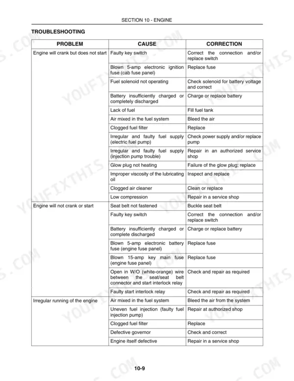
This 701-page New Holland L140, L150 Repair Manual (OEM #87634745) tears into every system on your Skid Steer Loader, from the hydrostatic drive to the boom faceplate. Inside: complete wiring diagrams for the instrument cluster and starter circuit, hydraulic schematics covering the control valve and cylinder routing, and a troubleshooting section built around real symptoms like a hydraulic system that loses pressure or won't lift. You get the hydrostatic pump high pressure test procedure, spec code 29-19, right alongside the charge system pressure test at 29-14, so you're not eyeballing a gauge and hoping. The control valve is a 3-spool open center design, and that pump behind it is a gear pump, not a piston unit; know the difference before you start swapping parts. No more chasing a dead heater fan or a balky neutralizer with guesswork. Download it once, keyword-search any spec, and jump straight to the bookmarked section you need on the shop floor.
What's Inside This New Holland L140, L150 Repair Manual
| System | Pages | Key Topics |
|---|---|---|
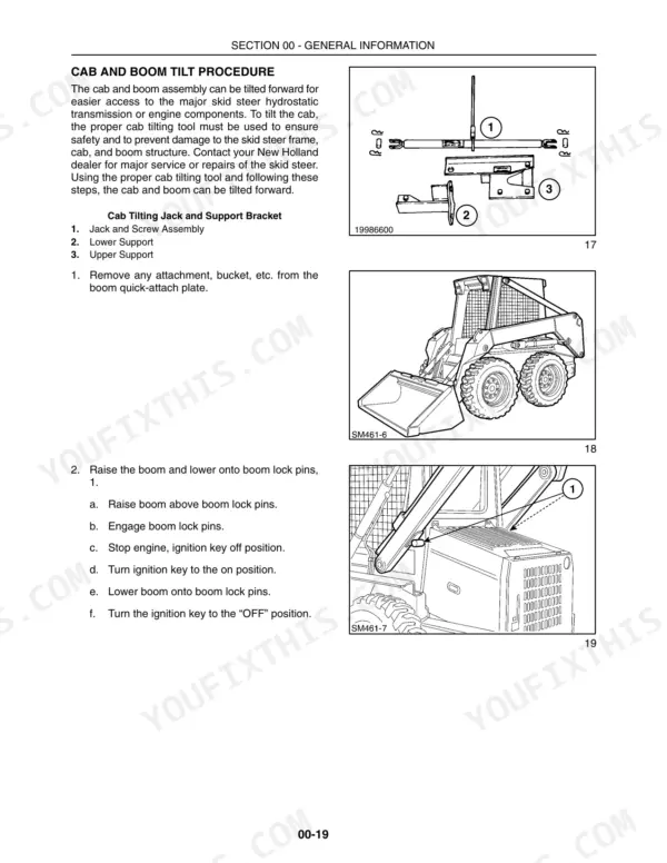
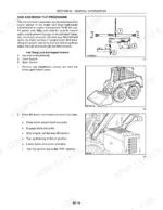
| General Information | 19-66 | Hardware Torque Specifications, Hydraulic Tubes and Fittings, Lubricants and Coolants, Sealants, Cab and Boom Tilt Procedure, Craning the Skid Steer |
| Engine | 67-176 | Engine Removal, Engine Disassembly Sequence, Engine Component Maintenance, Fuel System, Cooling System, Fuel Injection Timing |
| Hydrostatic Transmission | 177-278 | Hydrostatic Drive System Testing, Hydrostatic Pumps, Hydrostatic Motor, Hydrostatic System Controls, Neutralizer Assembly, Drive Control Adjustment Procedure |
| Brakes and Controls | 279-296 | Parking Brake, Parking Brake Removal and Inspection, Troubleshooting, Testing |
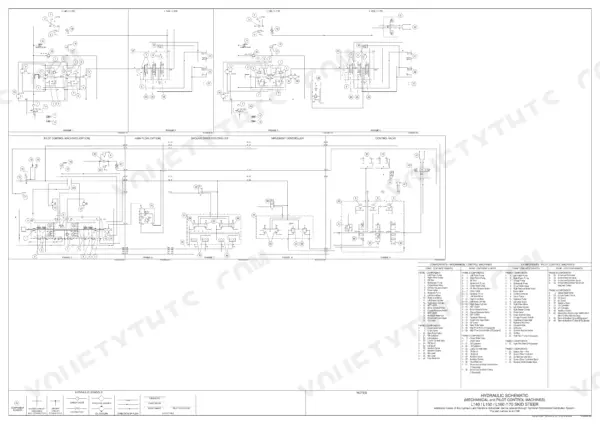
| Hydraulic System | 297-390 | Hydraulic System Testing, Control Valve, Hydraulic Pump, Cylinders, Pedal Controls, Hydraulic Cooling, Filter, Reservoir System |
| Towing Hooks and Ballasting | 391-392 | Rear Counterweights, Rear Counterweight Support Removal |
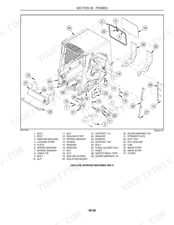
| Frames | 393-426 | Cab and ROPS, Cab and ROPS Removal, Cab and ROPS Reinstallation, ROPS Removal (Cab Upgrade Machines Only), ROPS Reinstallation (Cab Upgrade Machines Only) |
| Axles and Wheels | 427-460 | Axles, Axle Housing Assembly Removal, Final Drive, Tires/Wheels, Tire and Track Installation, Loader Boom Stop Adjustment |
| Cab Climate Control | 461-468 | Switch and Control Panel, Switch Wiring, Relay and Fuse Block, Heater Core, Heater Shutoff Valve, Heater Fan Assembly |
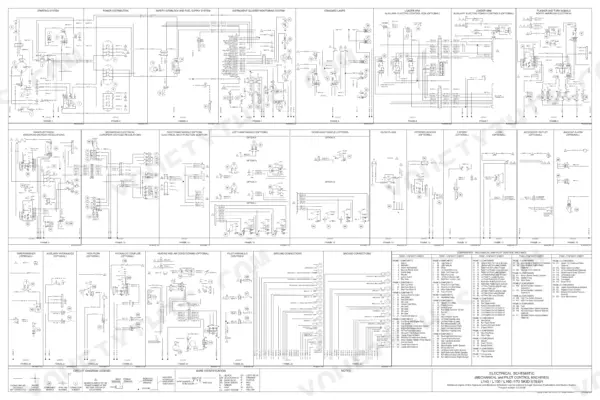
| Electrical System | 469-616 | Instrument Cluster, Battery, Alternator, Starter, Fuel System Electrical Components, Electrical Diagrams |
| Front Loader (Boom and Mounting Plate) | 617-660 | Buckets, Boom Lock Pins and Linkage, Attachment Mounting Plate, Boom and Cylinder Pivot Pins, Boom, Upper and Lower Link, Loader Faceplate |
| Accessories | 661-686 | Back-Up Alarm, Block Heater (Engine), Electric Power Supply, Exhaust and Aspirator Precleaner Muffler, Horn, Warning Lights |
| Platforms, Cab, Bodywork, and Decals | 687-698 | Seat and Seat Pan Support, Seat Removal, Seat Reinstallation, Safety Decals, ROPS Removal, ROPS Reinstallation |
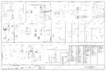
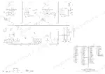
| Electrical / Hydraulic Schematics | 699-701 |
Quick Reference Specifications
| Specification | Value | Page |
|---|---|---|
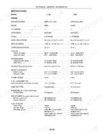
| Control valve | 3 Spool Open Center | p. 49 |
| Chain case (final drive) | 5.7 L (1.5 gal.) | p. 49 |
| Ignition system protection | Fuse 15 amps | p. 49 |
| Main system relief | 170-176 bar (2500-2600 PSI) | p. 49 |
| Engine Crankcase Capacity w/Filter | 5.5 L | p. 49 |
| Cooling System Capacity | 9.3 L | p. 49 |
| Fuel Tank Capacity | 37.8 L | p. 49 |
| Hydraulic System Capacity | 18.9 L | p. 49 |
| Main System Relief Valve Pressure | 170 - 177 bar | p. 304 |
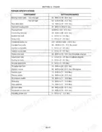
| Boom Cylinder Piston Locknut Torque | 231 N·m | p. 305 |
| Boom Cylinder Upper Pivot Pin Torque | 38 N·m | p. 305 |
| Axle Housing Mounting Bolt Torque | 190 N·m | p. 430 |
New Holland L140, L150 Common Problems This Manual Covers
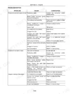
New Holland L140 and L150 hydraulic pressure drops under load and boom arms will not raise.
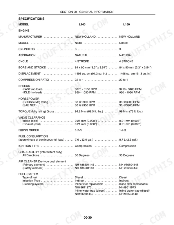
Inspect the inlet line for blockages as shown on page 307. Test the main system relief valve and verify it holds 170 to 177 bar (2500 to 2600 PSI). If pressure is low, check the gear pump output to ensure 40.1 L/min (10.6 GPM) at 2900 RPM for the L140.
Manual Section: Hydraulic System Troubleshooting p. 307Hydrostatic drive system feels sluggish on one side or the machine stops moving completely.
Remove the chain case cover and inspect the primary drive chain. Check the chain tension on page 282, ensuring a 6 mm (0.25 inch) deflection with 4.5 kg (10 pounds) of force. If the L140 chain is stretched beyond its 1174.75 mm length, replace it immediately.
Manual Section: Brakes and Controls p. 282Parking brake slips on steep inclines or emits a loud continuous grinding noise.
Inspect and repair the brake pads if worn. Install the replacement pads and torque the caliper retaining bolts to 70 Nm (52 pound-feet) as specified on page 293. Test the parking brake engagement to verify it holds the machine securely before returning it to service.
Manual Section: Parking Brake System Troubleshooting p. 293Electrical system fails to charge the battery and the starter motor cranks slowly.
Test the alternator output using a multimeter. Verify the alternator delivers a normal output of 12 V and 40 A as detailed on page 478. If the output falls below this specification, inspect the wiring harness for corrosion or replace the alternator assembly entirely.
Manual Section: Alternator System Testing and Troubleshooting p. 478Frequently Asked Questions
How do I reset New Holland L150 error codes?
To reset accumulated fault totals on the Advanced Instrument Cluster (AIC), when a fault history is being displayed, press and hold the road light button to set the accumulated fault total being displayed to zero. Alternatively, when “CLEAR” is displayed in the text display, press the system enable button to set all accumulated fault totals to zero. The maximum number of faults the instrument cluster can record is 256. p. 542
What are the torque specifications for New Holland L140 engine cylinder head bolts?
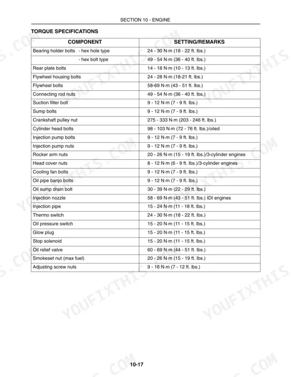
The cylinder head bolts for the L140 engine should be tightened to a torque of 98 - 103 N·m (72 - 76 ft. lbs.) when oiled. This is a critical specification for engine assembly. p. 83
How do I reset the hydraulic pressure on a New Holland L150?
The hydraulic system's charge pressure and high-pressure relief valves are factory set and are not adjustable. If a relief valve is found to be incorrectly set or not within specifications (e.g., 306 bar (4500 PSI) for high-pressure relief valves), it must be replaced with a new valve cartridge. p. 195
What are the torque specifications for the New Holland L150 brake assembly?
For the brake assembly, the Brake Support Mounting Bolt Torque (Center) is 26 N·m (230 pound-inches), and the Brake Support Mounting Bolt Torque (Outer Two) is 88 N·m (65 pound-feet). When reassembling, the caliper retaining bolts should be tightened to a torque of 70 N·m (52 pound-feet). p. 293
Will this New Holland L140 Repair Manual download right away?
Immediate download of the complete 701-page searchable Repair Manual. Access it on any device, from a laptop at your desk to a phone in the field.
Does this New Holland L140 manual allow printing?
Yes. Many mechanics print the section they need for their own shop and bring it to the bench.
Are electrical wiring diagrams included in this New Holland L140 Repair Manual?
Yes, full electrical schematics are included with wire colors, connector locations, and circuit descriptions.







Reviews
There are no reviews yet.