
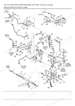
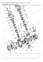
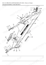
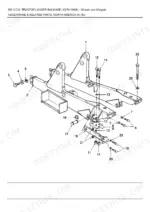
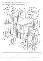
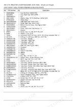
Part of the New Holland Parts Manuals.
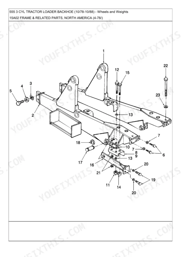
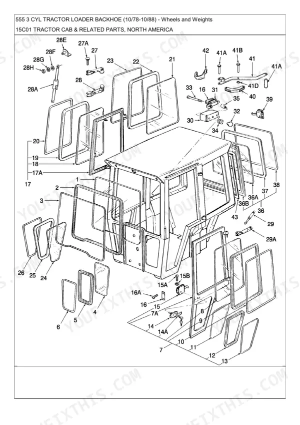
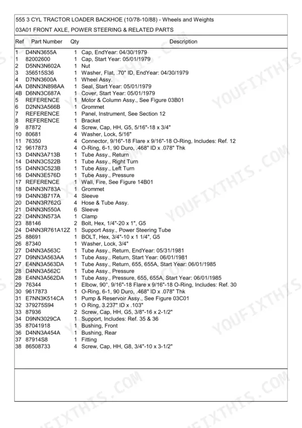
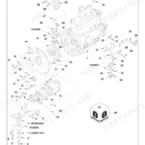
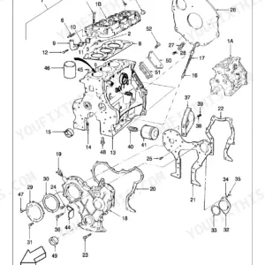
When you need the exact replacement numbers for your 1978-1988 Ford 555 Tractor Loader Backhoe, this 561-page Ford 555 Parts Catalog PDF breaks down the entire machine from the front axle to the swinging drawbar. You get highly detailed exploded views of the diesel engine block, power steering cylinders, and the complete torque converter transmission. Open to any assembly to find full parts lists with factory cross-references and clear component identification. Verify that your front end requires the 5.50 x 16 Wheel Assembly (Replaces D4NN1007A) and order the correct 1/2-inch washers without second-guessing. Stop wasting money on the wrong components. Grab this bookmarked download, pull it up on your phone at the parts counter, and get your equipment back in the dirt.
Complete the set for your Ford 555
What's Inside This Ford Ford 555 Parts Manual
| System | Pages | Key Topics |
|---|---|---|
| Fuel System | Fuel Injection Pump, Carburetor Assembly, Fuel Pump Assembly, Fuel Filter Kit, Engine Primer Ether System | |
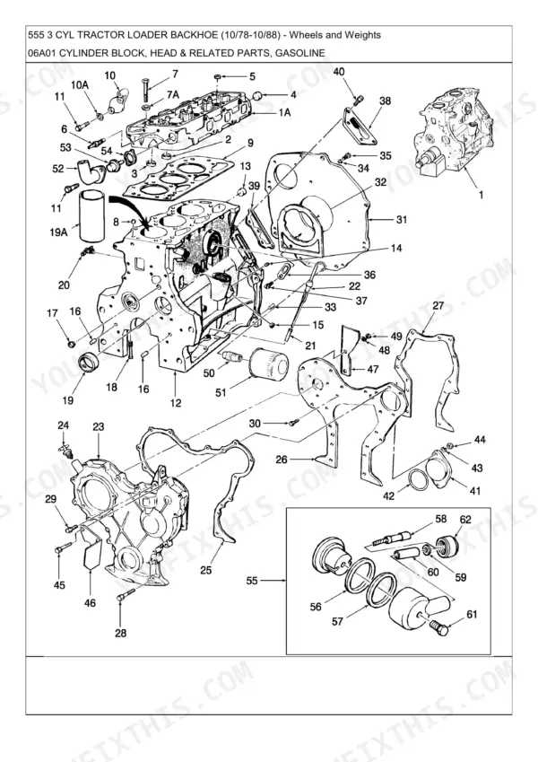
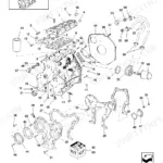
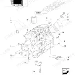
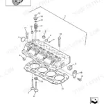
| Engine | Cylinder Block & Head, Crankshaft, Camshaft & Rocker Arm, Pistons & Connecting Rods, Oil Pump & Oil Pan, Manifold & Exhaust System, Engine Gasket Kits, Engine Overhaul Kits | |
| Electrical System | Alternator Assembly, Starting Motor, Distributor Assembly, Instrument Panel, Headlamp Assembly, Rear Lamp, Flasher & Signal Lamps, Stop & Tail Lights, License Plate Lamps, Horn Assembly, Back-Up Alarm | |
| Clutch & Transmission | Manual Reversing Transmission, Power Reverse Torque Converter Transmission, Torque Converter, Clutch & Gears, Single Clutch Assembly, Oil Distributor | |
| Rear Axle, Differential & Brakes | Rear Wheel Weights, Handbrake | |
| Front Axle & Four-Wheel Drive | Front Wheels, Front Axle, Power Steering Cylinder, Differential Box, Driveshafts, Reduction Gears, Steering Arms, Drive Shaft & Shield, Transfer Case, Transfer Case Controls, Center Housing Internals, Front Support | |
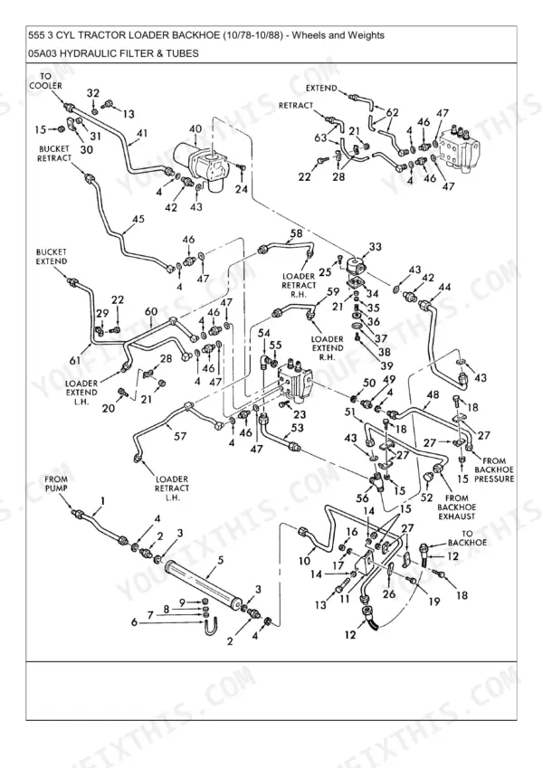
| Hydraulics & 3-Point Hitch | Control Valve Assembly, Control Valve, Hydraulic Pump, Swinging Drawbar | |
| Body & Operator Station | Cab Rear Panels, Tractor Cab, Cab Panels & Trim, Swivel Seat Assembly, Suspension Seat Assembly, Fenders, Frame & Related Parts, Engine Covers & Noise Insulation, Rollover Protection System | |
| Wheels, Weights & Accessories | Front Wheels, Front End Weight, Rear Wheel Weights, Reflectors |
Quick Reference Specifications
| Specification | Value | Page |
|---|---|---|
| Screw, Cap, HH, G5, 3/8"-16 x 1-1/4" | 3/8"-16 x 1-1/4" | p. 146 |
| Screw, Cap, HH, G5, 3/8"-16 x 1" | 3/8"-16 x 1" | p. 146 |
| O-Ring, .239" ID x .070" Thk | .239" ID x .070" Thk | p. 186 |
| O-Ring, 5-1, 90 Duro, .414" ID x .072" Thk | .414" ID x .072" Thk | p. 186 |
| Hose Assy., 53" Lg. | 53" Lg. | p. 445 |
| Hose Assy., 20-3/4" Lg. | 20-3/4" Lg. | p. 445 |
Ford Ford 555 Common Problems This Manual Covers
Ford 555 brake failure, can't find the correct seal kit part number for the brake assembly
Check the brake system components exploded view on pages 15 through 18. Page 16 lists two dust seals and two brake seal assemblies for the pedal linkage, and page 18 shows a matching 1/2 inch washer confirming the sub-assembly. Match the item numbers against the parts list column to pull the exact seal kit part number.
Manual Section: Brake System Components p. 16Front wheel drive differential box won't hold pins in place, need correct bushing and pin part numbers
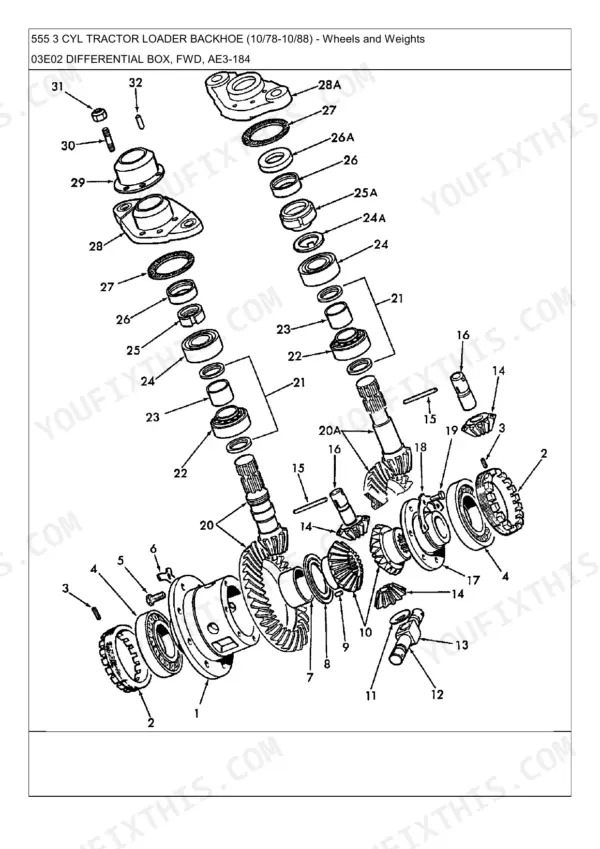
Check the differential box FWD exploded view on page 443. The parts list identifies a bushing with a 2 inch ID by 1-1/2 inch bore and matching pins ranging from 1-1/4 inch to 2 inch diameter. Match the reference number stamped next to each pin or bushing on the diagram to the parts list column before ordering.
Manual Section: Differential Box, FWD p. 443Fuel injection pump supply hose is cracked and leaking, can't locate the replacement hose assembly part number
Check the fuel injection pump parts breakdown on page 445. The supply hose assembly is listed at 53 inches long, with a shorter 20-3/4 inch hose also shown on the same page for a different routing. Match the item number on the exploded view to the parts list column to confirm which length fits your serial range.
Manual Section: Fuel Injection Pump p. 445Hydraulic control valve is leaking at the spool, need the correct O-ring part number for rebuild
Check the control valve assembly exploded view on page 92. The spool O-ring is listed as a 12-1 compound, 90 duro.924 inch ID by .116 inch thick. Cross-reference the item number shown next to the spool bore in the diagram against the parts list column to confirm the correct O-ring before ordering a rebuild kit.
Manual Section: Control Valve Assembly p. 92Fuel filter housing leaks after service, can't find the correct O-ring part numbers for the fitting
Check the fuel system parts breakdown on page 186. The filter housing O-ring is listed at .239 inch ID by .070 inch thick, with a larger 5-1 compound O-ring at .414 inch ID by .072 inch thick shown on the same page for the line fitting. Match the item number in the diagram to the parts list column before ordering.
Manual Section: Fuel System p. 186Torque converter oil distributor hardware is missing, need the correct cap screw part number and size
Check the torque converter and oil distributor parts breakdown on pages 154 through 157. Page 155 lists a self-locking cap screw at 3/8 inch-24 thread by 1/2 inch long, alongside several other cap screw lengths for the same housing. Match the item number on the exploded view to the parts list column to confirm the correct hardware size.
Manual Section: Torque Converter, Oil Distributor p. 155Frequently Asked Questions
What are the replacement specifications for Brake seal kit?
A Seal Assy. with part number 86576339 is specified for the brakes and brake controls. Two units are required for this assembly. p. 16
What are the replacement specifications for Hydraulic seal and hose assemblies?
For hydraulic lines and hoses, a Hose Assy. with part number 7706573 and a length of 53" Lg. is specified. Additionally, an O-Ring with part number 167269 has dimensions of 10-1, 90 Duro, .755" ID x .097" Thk. p. 445
What are the specifications for the front wheel assembly for a 2WD Ford 555 backhoe?
For 2WD front wheels, a Wheel Assy. with part number 83946635 is specified, measuring 5.50 x 16. This assembly replaces part number D4NN1007A. p. 2
What is the weight of the front end weight for a Ford 555 backhoe?
The front end weight for a Ford 555 backhoe is specified as 325 Lb. (147.73 KG) with part number E1NN3A370AC29Z1, and was applicable until 12/31/1983. p. 8
What are the specifications for the rear wheel weights for a 24" wheel on a Ford 555 backhoe?
For 24" rear wheel weights, a Weight with part number C9NN1A002E is specified, weighing 85 Lb. Twelve units are required, with a start year of 01/01/1978. p. 12
What do I get after purchasing this Ford 555 manual?
You get a 561-page searchable PDF that downloads instantly after checkout. Open it on your laptop, tablet, or phone, and bring it right to the shop floor.
Am I free to print this Ford 555 Parts Catalog?
Yes. Print the sections you need to take out to the shop for your own use. Standard letter or A4 paper works.







Reviews
There are no reviews yet.