
Part of the New Holland Repair Manuals.
This is the New Holland service manual for the TC4.90, TC5.70, TC5.80 and TC5.90 straw walker combines. It is part number 47881811, in English, dated May 2015.
This is the shop book, not the operator's handbook. It covers the traction gearbox, 10/75 final drives, hydrostatic drive, brakes, steering, hydraulics, threshing, separation, cleaning and unloading, with specs and torques. Electrical schematics and fault codes for the UCM, RHM, LCP, engine ECU and SCR DCU take up the largest part of the book.
What's Inside This New Holland TC4.90, TC5.70, TC5.80, TC5.90 Manual
| System | Pages | Key Topics |
|---|---|---|
| Introduction and Engine | 1-88 | Safety Rules, Manual Navigation, Part Identification, Engine Removal and Installation, Air Compressor, Compressed Air Tank, Relief Valve |
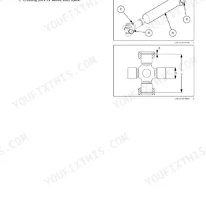
| Transmission | 89-230 | Mechanical Transmission, External Controls, Gearbox Housing, Drive and Driven Shafts, Shifting Disk System, Differential, Articulated Half-Shafts |
| Front Axle System | 231-250 | 10/75 Final Drive Specifications and Torques, Sectional Views, Final Drive Removal, Disassembly, Assembly and Installation |
| Rear Axle System | 251-268 | Non-Powered Rear Axle, Wheel-Hub Sectional View, Rear Axle Removal and Installation, Wheel-Hub Disassembly and Assembly |
| Hydrostatic Drive | 269-330 | Shuttle Spool Valve, Reservoir and Cooler, Bypass Valve, Sauer Danfoss Pump and Motor Specifications, Hydrostatic Schema, Filling and Start-Up, Troubleshooting |
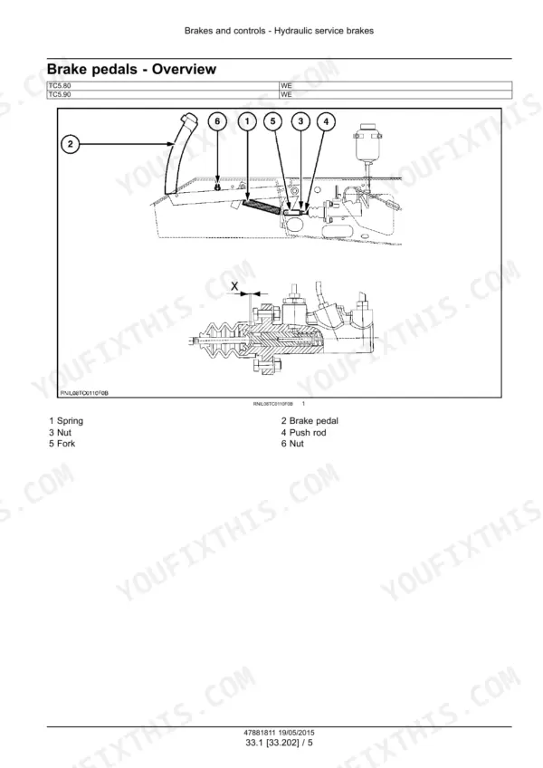
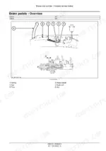
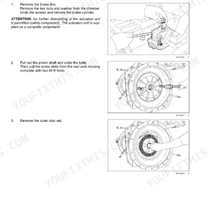
| Brakes and Controls | 331-364 | Hydraulic Service Brakes, Brake Torques, Brake Disks, Brake Pedals, Master Cylinder, Brake Adjustment, Parking Brake |
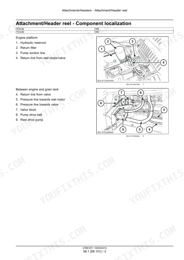
| Hydraulic Systems | 365-424 | Hydraulic Schema, Reservoir Breather, Oil Filters, Hydraulic Pumps, Stacked Control Valves, Remote Control Valves, Straw Chopper Clutch Valve, Reel Hydraulics |
| Steering | 425-452 | Power Steering Control Valve, Relief and Shock Settings, Valve Disassembly and Assembly, Steering Hydraulic Schema, Steering Pump |
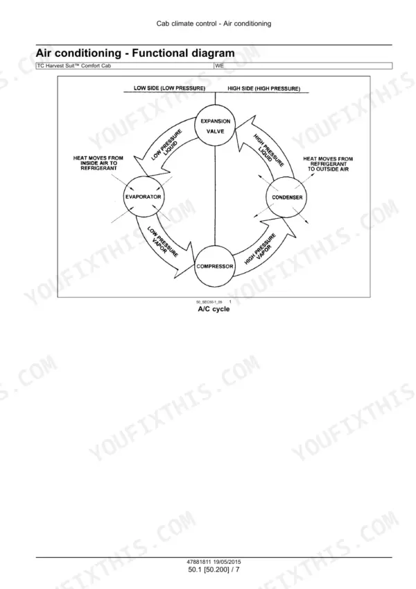
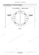
| Cab Climate Control | 453-506 | Refrigerant and Lubricant, Sanden Compressor Specifications, Condenser, Receiver/Dryer, System Checks, Filling, Magnetic Clutch, Troubleshooting |
| Electrical - System General | 507-545 | Fuses, Relays, Electrical Specifications, Harness Repair Tools, Electrical Standards, Component Reference Tables |
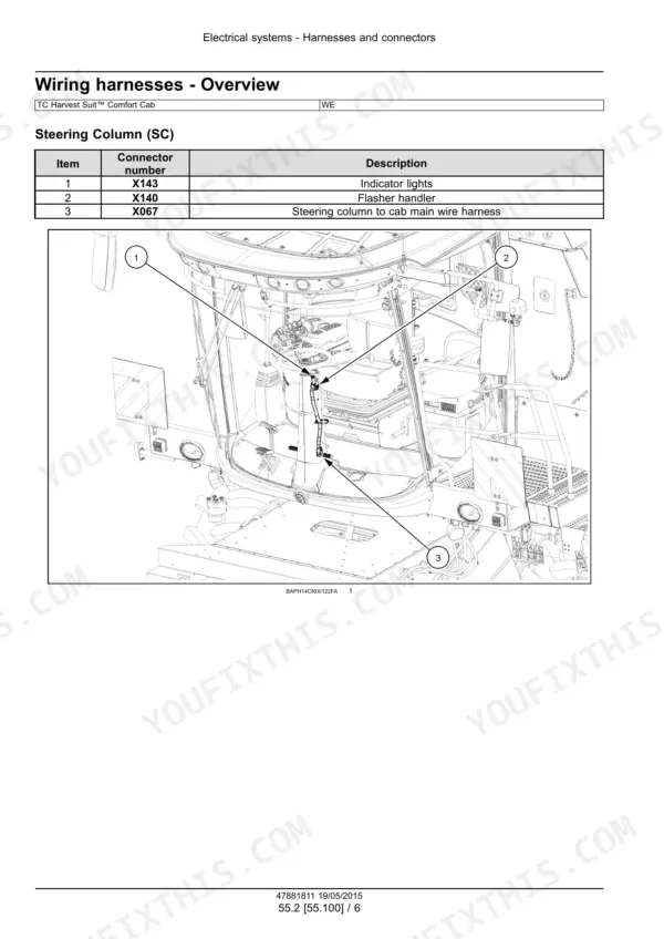
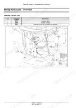
| Electrical - Harnesses, Connectors and Schematic Sheets | 546-1127 | Harness Overview, Electrical Schematic Sheets (Power Distribution, Engine, Drives, Lighting, HVAC, CAN Networks), Connector Diagrams |
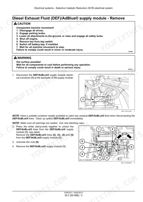
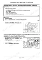
| Electrical - SCR, HVAC, Sieve, Precision Farming and Reverser Controls | 1128-1211 | SCR Supply and Dosing Modules, HVAC Controls and Gauge Diagnosis, Sieve Electric Control, Precision Farming, Moisture Sensor Adjustment, Reverser Motor |
| Fault Codes (DTC) - UCM, RHM and LCP | 1212-1875 | Fault Code Index, UCM Sensor and Relay Faults, Supply-Voltage Tests, Harness Continuity, CAN Diagnostics, RHM Switch Faults, LCP Lighting Faults |
| Fault Codes (DTC) - Engine ECU and SCR DCU | 1876-2288 | ECU Oil-Pressure and Engine Sensor Faults, Injector Diagnostics, Engine CAN Faults, DCU Supply Tests, SCR Temperature Sensors, DEF Pressure and Dosing |
| Attachments / Headers | 2289-2310 | Header Reel Localization, Belt-Feeding Components, Belt-Feeding Sectional View, Removal and Installation |
| Product Feeding | 2311-2340 | Feeder Housing, Feed Chain, Lower Shaft, Feeder Drive Shaft, Length-Of-Cut Gearbox, Slip Clutch, Feeder Reversing Gear |
| Threshing | 2341-2388 | Threshing Overview, Drum, Rasp Bars, Variator Belt and Adjustment, Drive and Driven Disks, Concave Specifications, Threshing Drive |
| Separation | 2389-2420 | Beater, Beater Shaft, Straw Walkers, Walker Supports, Front and Rear Shafts |
| Residue Handling | 2421-2440 | Straw Chopper Drive, Drive-System Disassembly and Assembly, Clutch Support and Bearings, Clutch Disk Removal and Installation |
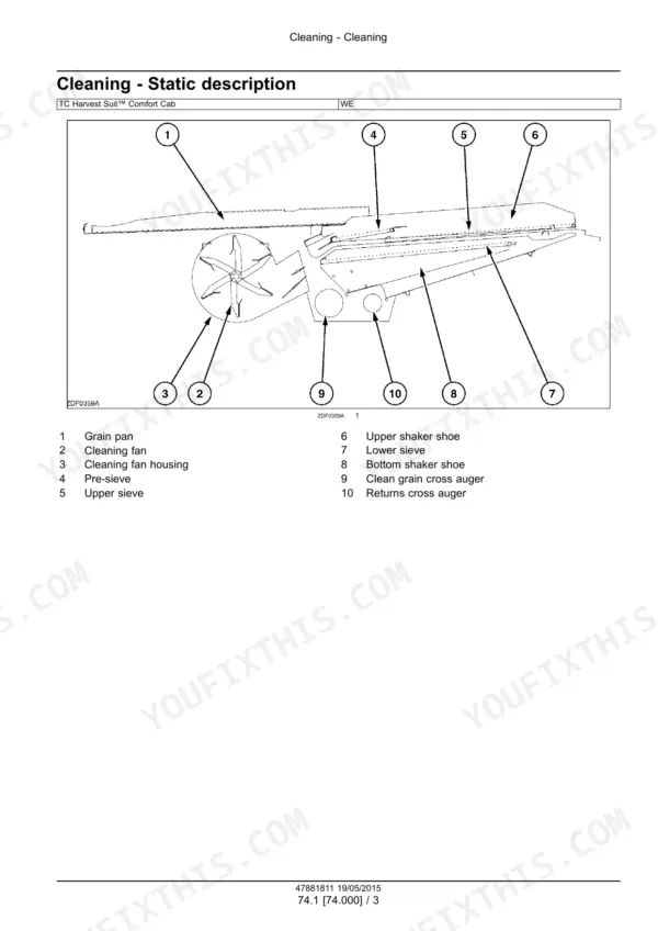
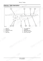
| Cleaning | 2441-2556 | Cleaning Drive, Grain Pan, Fixed Shaker Shoe, Smart Sieve, Shaker Connecting Rods, Fan Housing, Fan Variator, Tailings Return Elevator |
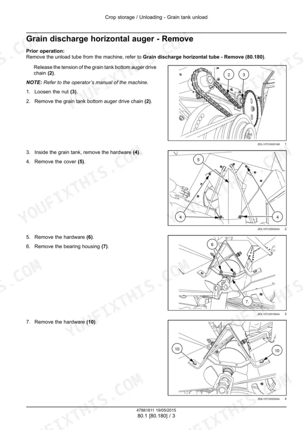
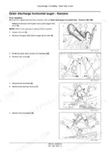
| Crop Storage / Unloading | 2557-2606 | Horizontal Unloading Auger, Unloading Tube, Clean Grain Elevator, Lower Grain Auger, Elevator Chain, Tank Filling Auger |
| Platform, Cab, Bodywork, Decals and Special Tools | 2607-2645 | Side Shields, Cab Roof, Cab Front Window, Window Locking Tools, Special Tool Index |
Quick Reference Specifications
| Specification | Value | Page |
|---|---|---|
| Engine code, TC5.80 (FPT NEF Tier 4A, Europe) | F4HFE613V*A003 | p. 3 |
| Engine code, TC5.90 (FPT NEF Tier 4A, Europe) | F4HFE613U*A006 | p. 3 |
| Traction gearbox oil capacity | 19 liters (5 US gal) | p. 212 |
| Final drive oil capacity (10/75 final drive) | 5.5 liters (1.45 US gal) | p. 234 |
| Wheel nuts tightening torque (10/75 final drive) | 610-732 Nm (450 - 540 lb ft) | p. 234 |
| Final drive to traction beam bolt torque | 440 Nm (325 lb ft) | p. 234 |
| Brake shoe bolts tightening torque (TC5.80, TC5.90) | 635 - 705 Nm (468 - 520 lb ft) | p. 334 |
| Hydrostatic pump displacement, TC4.90 / TC5.70 / TC5.80 | 75 cc/rev | p. 284 |
| Hydrostatic pump displacement, TC5.90 | 100 cc/rev | p. 284 |
| Hydrostatic pump rated speed at 2100 rpm engine, TC4.90 / TC5.70 / TC5.80 | 3000 rpm | p. 284 |
| Hydrostatic pump rated speed at 2100 rpm engine, TC5.90 | 2700 rpm | p. 284 |
| Hydrostatic pump flow at rated speed, TC4.90 / TC5.70 / TC5.80 | 225 l/min (59 US gpm) | p. 284 |
| Hydrostatic pump flow at rated speed, TC5.90 | 270 l/min (71 US gpm) | p. 284 |
| Hydrostatic charge pump pressure | 26 bar (377 psi) | p. 284 |
| Hydrostatic motor case pressure, maximum (cold start) | 5 bar (72.5 psi) | p. 285 |
| Main hydraulic pump maximum pressure | 280 bar (4061 psi) | p. 390 |
| Lateral flotation hydraulic pump maximum pressure | 230 bar (3336 psi) | p. 390 |
| Steering pressure relief valve setting | 100 - 105 bar (1450 - 1523 psi) | p. 429 |
| Reel hydraulic pump maximum oil flow at 2100 RPM engine (TC5.80, TC5.90) | 33.6 l/min (8.9 US gpm) | p. 420 |
| A/C compressor oil capacity (Sanden SD7H15 / SD7H13) | 200 cc (Sanden SP-10) | p. 458 |
New Holland TC4.90, TC5.70, TC5.80, TC5.90 Common Problems This Manual Covers
Machine will not operate in either direction
The troubleshooting table in the Hydrostatic Drive chapter lists this exact symptom. The printed cause is that the control cable is not connected. The printed correction is to connect the control cable. The same chapter has the hydrostatic schema, the Sauer Danfoss pump and motor specs, and the filling and start-up procedure.
Manual Section: Hydrostatic transmission - Troubleshooting p. 326E0008-03 Dual axis sensor (lateral inclination) - voltage above normal or shorted to high source
Step 3 of this procedure in the Fault Codes (DTC) chapter checks for a faulty dual axis sensor. If the indicated resistance is less than 0.3 ohm, replace the dual axis sensor. Connect connector X-102, clear the fault codes and check for correct operation.
Manual Section: Electrical systems - FAULT CODES p. 1231E0164-05 Road lights relay - current below normal or open circuit
Step 3 of this procedure in the Fault Codes (DTC) chapter checks for a faulty supply fuse. Turn the ignition switch OFF and check supply fuses F-005 (20 A) and F-006 (20 A). If a fuse shows a fault, replace it, clear the fault codes and check for correct operation.
Manual Section: Electrical systems - FAULT CODES p. 1653E2026-07 (DTC EA) Pressure line blocked
The Fault Codes (DTC) chapter says Dosing Control Unit (DCU) A-030 has sensed that the pressure line is clogged. If the tested pressure is greater than 345 kPa (50 psi), the clog is verified. Remove the clog from the pressure line. Then bring the engine to normal operating temperature and run it under load until the fault clears.
Manual Section: Electrical systems - FAULT CODES p. 2268Frequently Asked Questions
Which combines does the New Holland TC4.90 / TC5.70 / TC5.80 / TC5.90 service manual cover?
The cover lists the TC4.90, TC5.70, TC5.80 and TC5.90, part number 47881811, English, May 2015. The engine table names only two engines. The TC5.80 has the F4HFE613V*A003 and the TC5.90 has the F4HFE613U*A006, both FPT NEF Tier 4A for Europe. The book prints no PIN or serial ranges. p. 1
How does the TC5.90 hydrostatic drive differ from the TC4.90, TC5.70 and TC5.80?
All four use a Sauer Danfoss 90 Series pump, but the TC5.90 has a larger one. The TC4.90, TC5.70 and TC5.80 run 75 cc/rev at 3000 rpm and deliver 225 l/min (59 US gpm). The TC5.90 runs 100 cc/rev at 2700 rpm and delivers 270 l/min (71 US gpm). Both figures assume 2100 rpm engine speed. Charge pump pressure is 26 bar (377 psi) on every model. p. 284
How much oil goes in the traction gearbox and the final drives?
The traction gearbox takes 19 liters (5 US gal) of oil. A 10/75 final drive takes 5.5 liters (1.45 US gal). p. 212
What are the wheel nut and final drive mounting torques?
On the 10/75 final drive, wheel nuts are 610-732 Nm (450 - 540 lb ft). The bolts holding the final drive to the traction beam are 440 Nm (325 lb ft). On the TC5.80 and TC5.90, brake shoe bolts are 635 - 705 Nm (468 - 520 lb ft). p. 234
Does the manual include wiring diagrams, hydraulic schematics and fault codes?
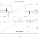
Yes. The electrical schematic sheets start on p.573 under Harnesses and connectors. They include sheet 01 overview, sheet 02 power distribution - starter and sheet 13 engine - Tier 4. There are hydraulic schemas for the hydrostatic transmission, the main hydraulic systems, the remote control valves and the steering. The FAULT CODES - DTC chapter starts on p.1212 and covers UCM, RHM, LCP, engine ECU and SCR DCU codes. Examples include E0164-05 Road lights relay and E2026-07 Pressure line blocked. p. 573






Reviews
There are no reviews yet.