Part of the New Holland Repair Manuals.
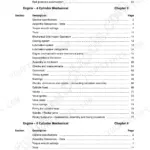
A U80B that lifts fine cold and sags by mid-afternoon usually comes down to one pressure reading, and this manual tells you what that reading should be. The New Holland U80B repair manual, publication 87728505 NA, runs 852 pages of factory procedure for the Loader Landscaper: General torque and lubricant charts, then Engine, Fuel System, Electrical, Steering, Power Train, Brakes, Hydraulics and Mounted Equipment, closing with the hydraulic and electrical schematics.
Guessing costs more than the book: the wrong seal kit, a second teardown after the first one missed the lock valve, a clutch pack cooked because nobody checked transmission oil temperature. You get removal and installation steps, pressure checks, troubleshooting charts and the specification tables behind them, including loader control valve and cylinder work.
It arrives as a PDF download, readable on a laptop at the machine and printable page by page, so the component you order matches the one you pulled.
What's Inside This Repair Manual
| System | Pages | Key Topics |
|---|---|---|
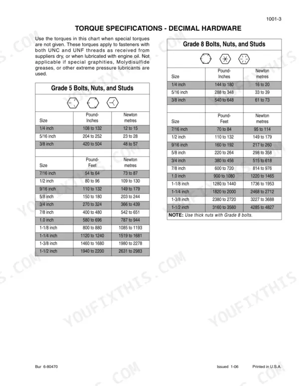
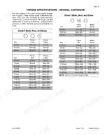
| General | 5-21 | Section Index - General (Standard Torque Specifications, Fluids and Lubricants, Metric Conversion Chart) |
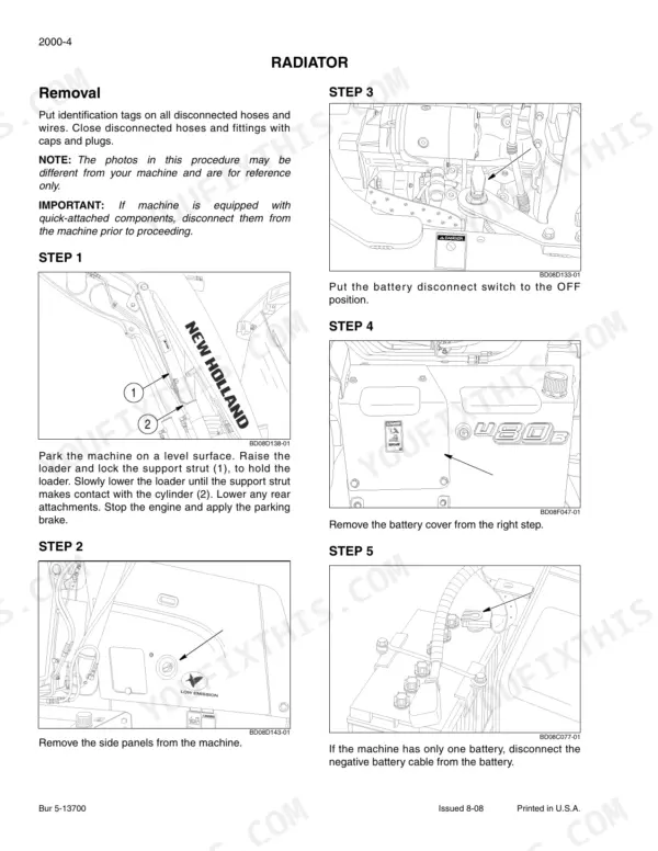
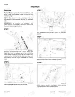
| Engine | 22-76 | Section Index - Engine (Engine and Radiator Removal and Installation, Stall Test, Diagnosing Engine Oil Consumption, Counter Balance Removal and Installation, Turbocharger Diagnosis Procedure Family 3 Engines) |
| Fuel System | 77-95 | In Vehicle Injector Pump Removal, Installation and Static Timing |
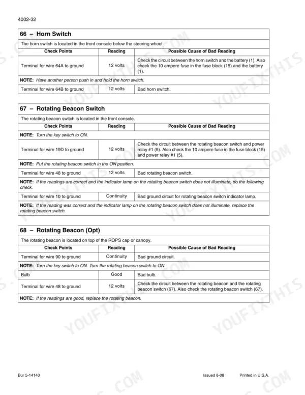
| Electrical | 96-192 | Section Index - Electrical (Removal and Installation of Electrical Components, Electrical Specifications and Troubleshooting, Batteries, Instrument Cluster) |
| Steering | 193-299 | Removal and Installation of Steering Components, Steering Specifications, Pressure Checks and Troubleshooting, Steering Control Valve, Steering Cylinders |
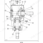
| Power Train | 300-552 | Removal and Installation of Power Train Components, Standard Transmission Specifications, Pressure Checks, And Troubleshooting, Wheels and Tires, Rear Axle and Planetaries |
| Brakes | 553-571 | Section Index - Brakes (Removal and Installation of Brake Components, Master Cylinder) |
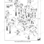
| Hydraulics | 572-720 | Section Index - Hydraulics (Removal and Installation of Hydraulic Components, Hydraulic System Specifications and Troubleshooting, Cleaning the Hydraulic System and Hydrostatic System, Loader Control Valve, Cylinders, Three Point Hitch Control Valve, Accumulator for Machines with Optional Glide Ride, Solenoid Valve for Machines with Optional Glide Ride, Flow Control Valve, Lock Valve) |
| Mounted Equipment | 721-849 | Section Index - Mounted Equipment (Pedals and Levers, Air Conditioning Troubleshooting, Air Conditioning System Service, Air Conditioning Components Service, Loader, ROPS Cab and Canopy, Standard and Mechanical Suspension Seat, Plug-In Weight) |
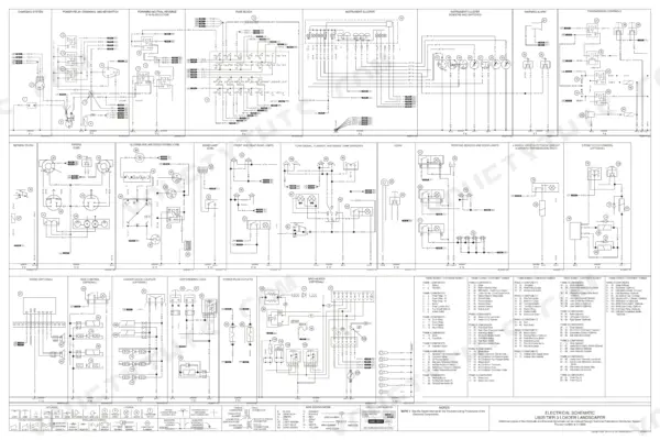
| Schematic Set | 850-852 | Hydraulic and Electrical Schematics |
Quick Reference Specifications
| Specification | Value | Page |
|---|---|---|
| Bolts for bearing caps | 120 Nm (89 pound-feet) | p. 246 |
| Bearing cap plug | 15 Nm (11 pound-feet) | p. 246 |
| Wheel nuts | 350 Nm (258 pound feet) | p. 256 |
| Rear wheel lug nuts | 1st phase 136 Nm (100 pound-feet), 2nd phase 271 Nm (200 pound-feet), 3rd phase additional 30 degrees | p. 303 |
| Mounting bolt for gear shift lever | 125 to 150 Nm (93 to 112 pound-feet) | p. 303 |
| Output of supply pump | 32 L/min to 68 L/min at 900 to 2200 r/min | p. 321 |
| Pump supply pressure (4WD) | 1248 to 1551 kPa, 12.5 to 15.5 bars at 900 to 2200 r/min | p. 321 |
| Pump Supply Pressure (Forward, Idle) | 1393 to 1427 kPa (202 to 207 psi) | p. 337 |
| Differential Lock Pressure | 1262 to 1317 kPa (183 to 191 psi) | p. 337 |
| Relief valves, item number 16 | 48 ± 5 lb-ft (65 ± 6.7 Nm) | p. 665 |
| Check valves, item number 20 | 90 ± 9 lb-ft (122 ± 12 Nm) | p. 665 |
| Receiver-Drier Oil Amount | 0.7 to 0.8 FL OZ (20 to 25 CC) | p. 792 |