

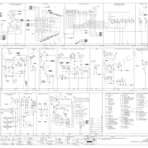
Part of the New Holland Repair Manuals.
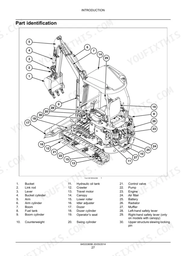
Track tension looks fine from the walkway, then the machine crabs on a slope and the chain rides the idler: the Tracks and Track Suspension section is where that gets settled. The answers come from New Holland publication 84533365B, the factory service book written for the E16B and E18B mini excavators, 879 pages delivered as a PDF.
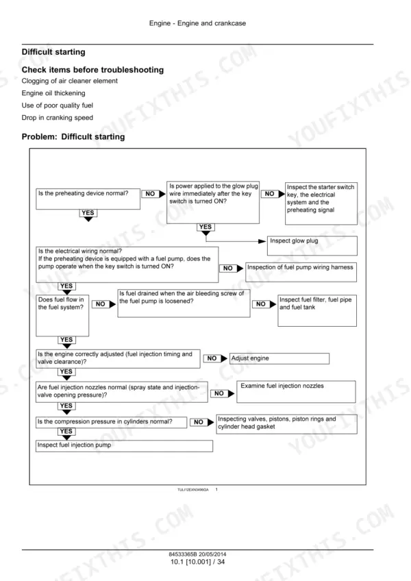
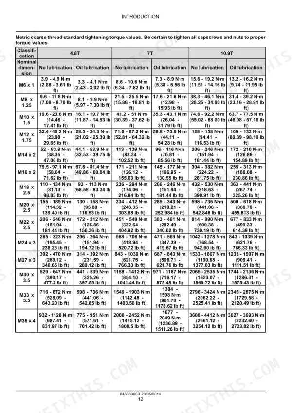
Coverage runs from the Mitsubishi L3E-31KBSA diesel through the variable displacement pump, main control valve, hand and foot pilot controls, swing and travel motors, undercarriage, boom, dipper and bucket, dozer blade, cab and the full electrical system. Torque tables, capacities, removal and assembly steps, hydraulic schematics and troubleshooting charts are all in it.
When it is just you, the machine and nobody to call, this is the document the dealer technician works from. Print the pages you need, take them out to the bench, and let them get dirty.
What's Inside This New Holland E16B, E18B Manual
| System | Pages | Key Topics |
|---|---|---|
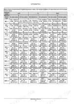
| Introduction | 6-33 | Foreword - Important Notice Regarding Equipment Servicing, Safety Rules, Personal Safety, Torque, Basic Instructions - How to Use Maintenance Standards and Precautions, Capacities |
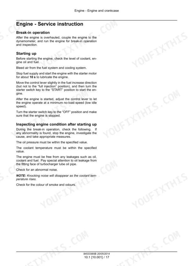
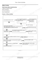
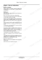
| Engine | 34-243 | Engine and Crankcase, Pan and Covers, Valve Drive and Gears, Cylinder Heads, Connecting Rods and Pistons, Crankshaft and Flywheel, Fuel Injection System, Throttle Linkage |
| Hydraulic Systems - 000 | 244-294 | Hydraulic Schematic, One-Speed E16B, Two-Speed E16B, E18B Standard Specification, Hydraulic Circuit Operation |
| Reservoir, Cooler, and Filters - 300 | 295-349 | Oil Reservoir Removal, Oil Reservoir Installation, Hydraulic Filters, Cooler Maintenance |
| Variable Displacement Pump - 106 | 350-383 | Pump General Specification, Dynamic Description, Pump Removal, Pump Installation, Pump Disassembly, Pump Assembly, Troubleshooting |
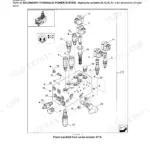
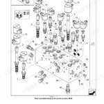
| Main Control Valve - 359 | 384-437 | Stacked Control Valves, Component Identification, Hydraulic Schema, Dynamic Description, Main Control Valve Removal, Main Control Valve Installation, Relief Valve Troubleshooting |
| Hydraulic Hand Control - 355 | 438-455 | Hand Control General Specification, Component Identification, Dynamic Description, Hand Control Disassembly, Hand Control Assembly, Troubleshooting |
| Hydraulic Foot Control - 356 | 456-469 | Pedal Control General Specification, Sectional View, Dynamic Description, Pedal Control Disassembly, Pedal Control Assembly, Troubleshooting |
| Hydraulic Swing System - 352 | 470-495 | Swing System General Specification, Component Identification, Dynamic Description, Swing Motor Removal, Swing Motor Installation, Swing Motor Disassembly, Swing Motor Assembly |
| Hydraulic Travel System - 353 | 496-545 | Travel System General Specification, Component Identification, Dynamic Description, Travel Motor Removal, Travel Motor Installation, Travel Motor Disassembly, Travel Motor Assembly |
| Frames and Ballasting | 624-645 | Upper Frame, Swing Ring Assembly, Ballasts and Supports |
| Tracks and Track Suspension | 646-693 | Track Frame and Driving Wheels, Tracks, Track Tension Units, Track Rollers |
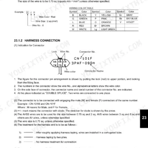
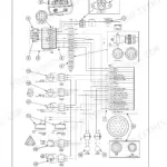
| Electrical Systems | 694-789 | Electrical System, Harnesses and Connectors, Engine Starting System, Cold Start Aid, Alternator, Battery |
| Booms, Dippers, and Buckets | 790-827 | Boom Pivoting Support, Boom, Dipper Arm, Bucket |
| Dozer Blade and Arm | 828-839 | Dozer Blade |
| Platform, Cab, Bodywork, and Decals | 840-879 | Cab, Operator Protections, Mechanically-Adjusted Operator Seat, Machine Shields and Guards, Fenders and Guards |
Quick Reference Specifications
| Specification | Value | Page |
|---|---|---|
| Joints for piping (with O-ring) 1/8 | 17 N·m ± 2 N·m | p. 20 |
| Joints for piping (with O-ring) 1/4 | 36 N·m ± 2 N·m | p. 20 |
| Sprocket screw tightening torque | 49.4 - 60.4 N·m (36.4 - 44.5 lb ft) | p. 510 |
| Travel motor fastening screw tightening torque | 49.4 - 60.4 N·m (36.4 - 44.5 lb ft) | p. 510 |
| Pressure of the engine ports | ≥ 3 bar (44 psi) | p. 544 |
| Engine Power | 11.2 kW at 2100 RPM | p. 24 |
| Engine Maximum Torque | 53.5 N·m at 1800 RPM | p. 24 |
| Engine Oil Pan Capacity | 3.0 L | p. 26 |
| Fuel Tank Capacity | 16 L | p. 26 |
| Hydraulic Oil Tank Capacity | 9 L | p. 26 |
| Cylinder Head Bolt Torque (Main) | 75.3 - 83.4 N·m | p. 38 |
| Cylinder Head Bolt Torque (Sub) | 19.6 - 29.4 N·m | p. 38 |
New Holland E16B, E18B Common Problems This Manual Covers
Track tension drifts out of adjustment
Pins and bushings wear, the chain stretches, and a slack track will climb the idler or throw itself in a tight turn. The Tracks and Track Suspension section covers the track frame and driving wheels, tracks, track tension units and track rollers.
Manual Section: Tracks and Track Suspension p. 646Machine pulls to one side traveling
When one track lags the other on flat ground, the fault is usually in the travel motor or the central joint rather than the undercarriage itself. The Hydraulic Travel System section gives the component identification, dynamic description, and full motor removal, disassembly and assembly.
Manual Section: Hydraulic Travel System - 353 p. 496Weak boom and arm under load
Cycle times stretch and the arm stalls in a dig when main relief pressure has fallen off or a spool is hanging up. The Main Control Valve section covers the stacked valve sections, hydraulic schema and relief valve troubleshooting.
Manual Section: Main Control Valve - 359 p. 384House creeps after the swing stops
An upperstructure that keeps drifting once the joystick centers points at the swing motor brake or its valving, not at the swing bearing. The Hydraulic Swing System section has the general specification, dynamic description, and swing motor removal, disassembly and assembly.
Manual Section: Hydraulic Swing System - 352 p. 470Vague joysticks, poor self-centering
Worn plungers and tired centering springs in the pilot control circuit leave the levers feeling dead off center and slow to return. The Hydraulic Hand Control section covers component identification, disassembly, assembly and troubleshooting.
Manual Section: Hydraulic Hand Control - 355 p. 438Debris in oil after a component failure
Metal from a failed pump or motor circulates through the tank and will take out whatever you install next if the system is not cleaned properly. The Reservoir, cooler, and filters section covers oil reservoir removal and installation.
Manual Section: Reservoir, Cooler, and Filters - 300 p. 345Head gasket failure and overheating
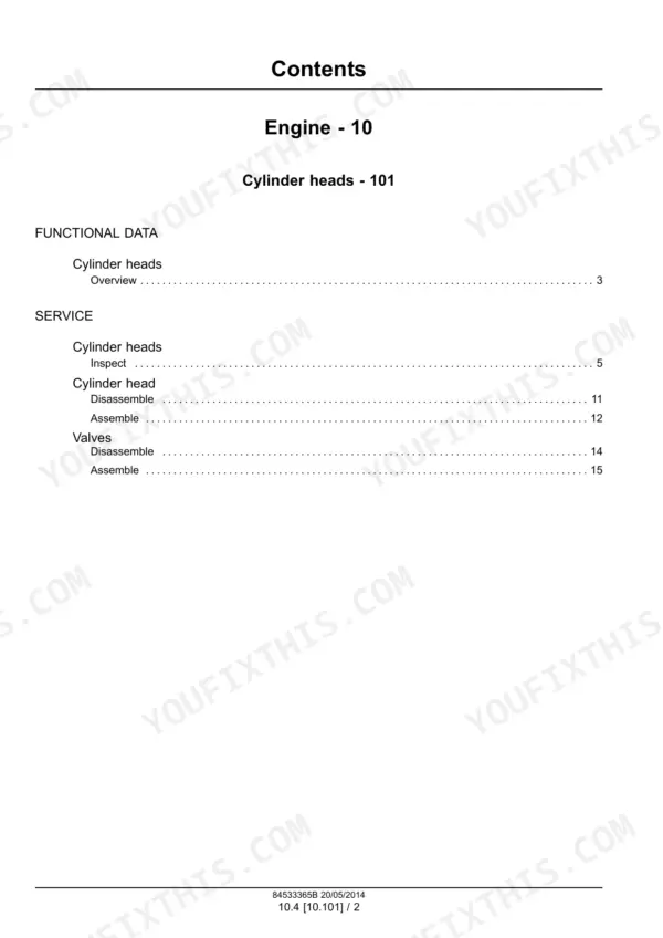
Coolant loss or a persistent overheat on the L3E-31KBSA usually ends with the cylinder head off. The Engine section gives the reassembly values: 75.3 to 83.4 N·m on the main cylinder head bolts and 19.6 to 29.4 N·m on the sub bolts.
Manual Section: Engine p. 38Frequently Asked Questions
Which machines and engine does this manual cover?
New Holland E16B and E18B mini crawler excavators fitted with the Mitsubishi L3E-31KBSA diesel. The general specification pages list operating mass as 1580 kg for the E16B with canopy and 1780 kg for the E18B with cab. p. 25
Are the hydraulic schematics included?
Yes. The Hydraulic Systems section opens with the hydraulic schematic and circuit operation, separated for one-speed E16B, two-speed E16B and E18B standard specification, so you can trace a circuit before cracking a single line loose. p. 244
Does it list fluid capacities for a service?
Yes, in the capacities pages near the front: 3.0 L engine oil pan, 16 L fuel tank and 9 L hydraulic oil tank. Torque tables for piping joints and hoses sit in the same introductory group. p. 26
How will I receive this New Holland E16B Service Manual?
All 879 pages arrive as one searchable PDF at checkout. Read it at the desk, then take the phone out to the machine.
Can I print a copy of this New Holland E16B Service Manual for the shop?
No restrictions at all. Print individual pages, full chapters, or the entire manual. The PDF is completely unlocked.





Reviews
There are no reviews yet.