
![New Holland W230 Repair Manual [Wheel Loader]](https://youfixthis.com/wp-content/uploads/2012/02/Manual_Download-300x300.jpg)
Part of the New Holland Repair Manuals.
Need the factory breakdown for your 2005 wheel loader? All 452 pages of this New Holland W50, W60, W70, W80 workshop manual PDF (OEM #604.13.577 English) focus on getting your machine back to factory condition. You get full electrical circuit diagrams for start interlocks and analog gauges, plus complete hydrostatic transmission plumbing schematics. Open up detailed troubleshooting charts for axle problems, brake system faults, and step-by-step procedures for rebuilding the articulated joint frame. Verify the engine displacement hits exactly 3108 cm³ and always grease the lips of new shaft seals before fitting them into the H1 lifting cylinder. Guessing specs leads to broken machinery. Grab this bookmarked digital download, jump instantly to your targeted system, and get the job done right.
What's Inside This New Holland W50–W80 Series Manual
| System | Pages | Key Topics |
|---|---|---|
| Safety Instruction | 7-18 | Fundamental Safety Instructions (Warnings and Symbols, Risks Resulting From Failure to Observe the Safety Instructions, Organizational Measures, Selection and Qualification of Personnel) |
| Service Data | 19-64 | Foreword, Si- and Additional Units (Quantities of Space and Mass, Time Related Quantities, Quantities of Force, Energy and Power) |
| Diesel Engine | 65-68 | - |
| Transmission | 69-104 | General (Safety Instructions, Explanations of Circuit Diagrams and Illustrations, Depressurizing the Hydraulic System, Principle: Hydrostatic Transmission) |
| General Information | 108-114 | General, Agreements and Definitions, Instructions Concerning the Safety at the Place of Work, Recommendations for Repair Operations |
| Removal and Installation of Axles | 115-119 | Front Axle, Rear Axle |
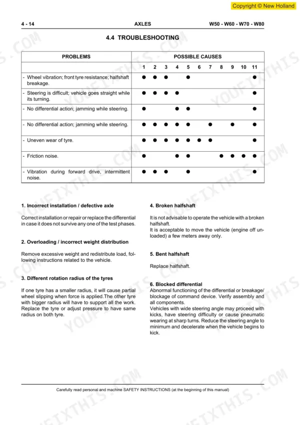
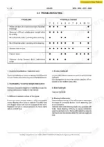
| Troubleshooting | 120-124 | Axle Problems and Diagnosis |
| General Specifications of Rear Axel | 125-156 | General Description, Technical Features, Overall Dimensions, Oil Change and Checks |
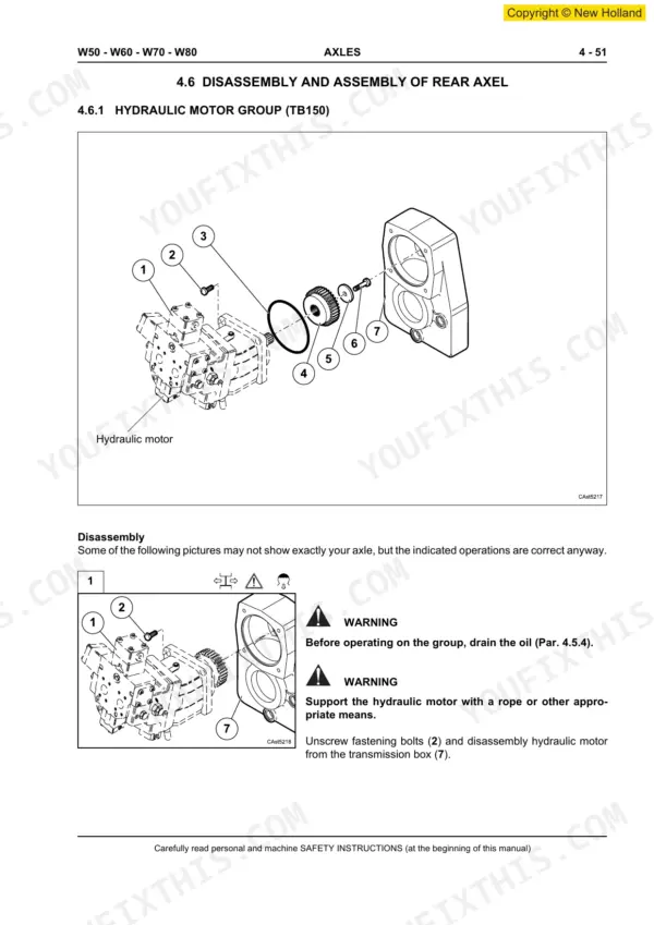
| Disassembly and Assembly of Rear Axel | 157-246 | Hydraulic Motor Group (Tb150), Hydraulic Motor Group (Tb138.5), Transmission Box Group (Tb150), Transmission Box Group (Tb138.5) |
| General Specifications of Front Axel | 247-268 | General Description, Technical Features, Front Axle Dimensions, Differential, Planetary Reduction, Torque Values |
| Disassembly and Assembly of Front Axel | 269-344 | Brake Disk Group, Epicyclic Reduction Gear Group (W50), Epicyclic Reduction Gear Group (W60 - W70 - W80), Wheel Hub Group (W50) |
| Steering | 345-364 | General (Safety Instructions, Explanations of Circuit Diagrams and Illustrations, Depressurizing the Hydraulic System) |
| Brake System | 365-386 | General (Safety Instructions, Explanations of Circuit Diagrams and Illustrations), Hydraulic Circuits Diagrams (Brake System: Standard Version, High Speed Version) |
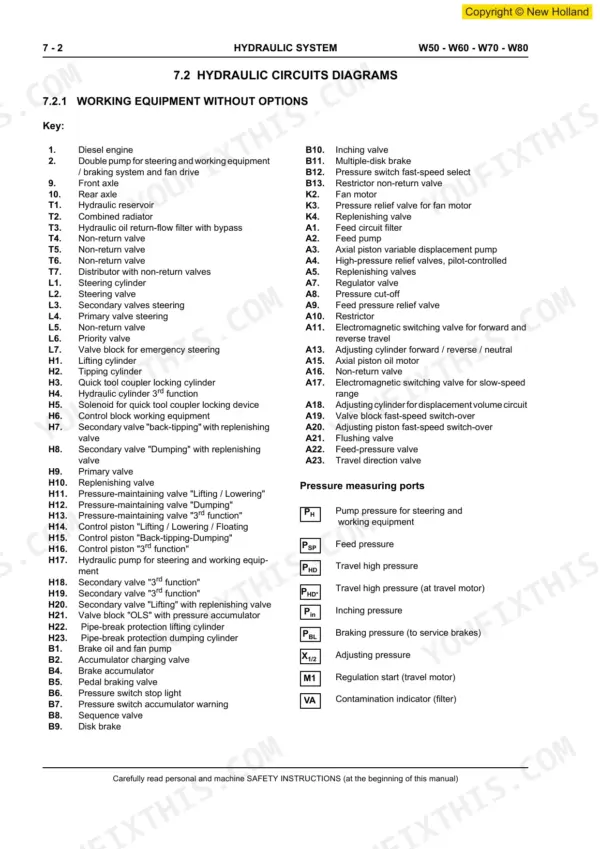
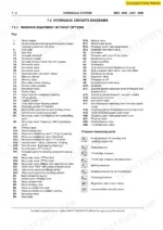
| Hydraulic System | 387-422 | Hydraulic Pump, Control Valves, Cylinders, Hydraulic Circuit Diagram, Relief Valve Settings, Filters, Oil Cooler |
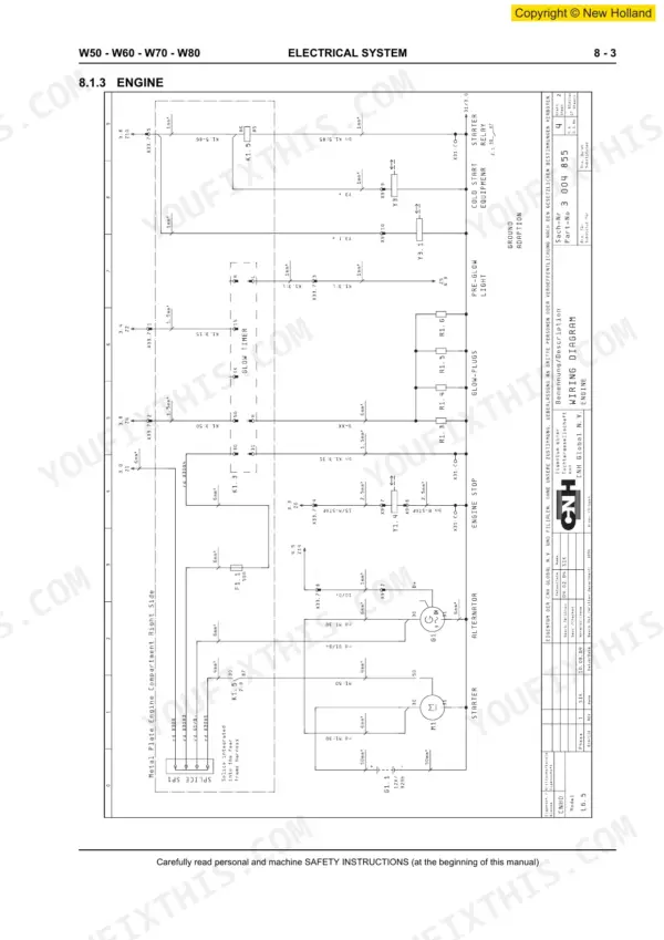
| Electrical System | 423-442 | Electrical Circuit Diagrams, W50-W60-W70-W80, N. 3 004 855, List of Contents, Engine, Start / Start Interlock, Signal Lamp |
| Frame | 443-452 | Repair of the Frame, Articulated Joint, Replacement of Parts |
Quick Reference Specifications
| Specification | Value | Page |
|---|---|---|
| Hydraulic System | SECTION 7 | p. 5 |
| Sealing elements such as O-rings, double lip seals, shaft seals and sleeves | must always be replaced | p. 110 |
| The lips of shaft seals | must be greased before fitting | p. 110 |
| Lifting cylinder (H1) leaking | Seal up cylinder | p. 417 |
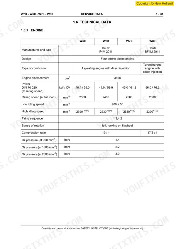
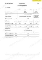
| Engine displacement | 3108 cm³ | p. 51 |
| Low idling speed | 900 ± 50 min⁻¹ | p. 51 |
| Hydraulic oil temperature for testing | 60 - 70 °C | p. 54 |
| Primary pressure relief (Working hydraulics) | 230 ± 10 bars | p. 54 |
| Accumulator precharge pressure | 20 ± 1 bars | p. 55 |
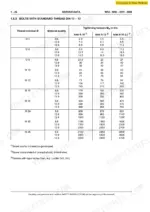
| Wheel-nut tightening torque | 500 Nm | p. 63 |
| Front axle weight | 230 kg | p. 64 |
| Lifting cylinder stroking time (bucket empty) | 6.0 ± 0.5 s | p. 54 |
New Holland W50–W80 Series Common Problems This Manual Covers
New Holland W80 loader shuts down mid-operation with electrical fault warning lit on the panel
Check the wiring diagram on page 427 and trace the harness for scorched insulation near the engine bay. Pull every fuse block and verify each fuse matches its specified current rating; a swapped or oversized fuse is the usual culprit. Tighten all battery and starter connections, then retest under load before returning the machine to service.
Manual Section: Electrical System p. 427Hydraulic boom won't lift and fluid is visibly leaking around the cylinder base
Inspect the lifting cylinder (H1) per page 417; if it's weeping, seal up the cylinder rather than just tightening the gland nut. Replace any O-rings and shaft seals you disturb, since sealing elements must always be replaced once removed and the seal lips need to be greased before fitting per page 110. Run the system at 60 to 70°C oil temperature per page 54 to confirm the leak is stopped under real working conditions.
Manual Section: Hydraulic System p. 417Loader bucks violently while carrying bales across rough ground
Verify the soft ride or air ride seat function is actually engaged; on rough terrain this circuit dampens boom bounce independent of ground speed. Check the accumulator precharge pressure against the 20 ± 1 bar spec on page 55, since a weak accumulator will let the boom float and slam instead of cushioning. Inspect the soft ride switch wiring for continuity if the function won't activate at all.
Manual Section: Hydraulic System p. 55Hydraulic pressure reads low in the boom circuit during working hydraulics test
Set up the test rig with oil at 60 to 70°C per page 54 and check primary pressure relief against the 230 ± 10 bar spec for working hydraulics. If pressure won't hold, walk both the lifting and dumping cylinders for external leaks per page 417 and seal up whichever one is dropping pressure. Recheck the reading after the fluid stabilizes at temperature, since a cold system will read falsely low.
Manual Section: Hydraulic System p. 54Return-to-dig response feels sluggish during repetitive pile loading cycles
Review the hydrostatic transmission adjustment procedures covering pressure cut-off and feed pressure regulation, since a drifting cut-off setting will delay the return stroke under repeated cycling. Confirm engine low idle sits at 900 ± 50 rpm per page 51, as a low idle drags down pump response between cycles. Check the transmission hydraulic schematic on page 75 to isolate whether the delay is in the pilot circuit or the main pump regulator.
Manual Section: Transmission p. 75Rear axle makes noise or shows uneven wear after extended field use
Work through the axle problems and diagnosis chart starting at page 120 to match the noise pattern to a likely cause before pulling anything apart. Check oil level and condition against the change intervals on page 147, since low or contaminated gear oil is the most common driver of premature wear. Torque the wheel nuts to 500 Nm per page 63 after any axle service, and confirm axle testing procedures are followed once reassembled.
Manual Section: Troubleshooting p. 120Frequently Asked Questions
What are the torque specifications for hydraulic pump mounting bolts on New Holland W50, W60, W70, and W80 wheel loaders?
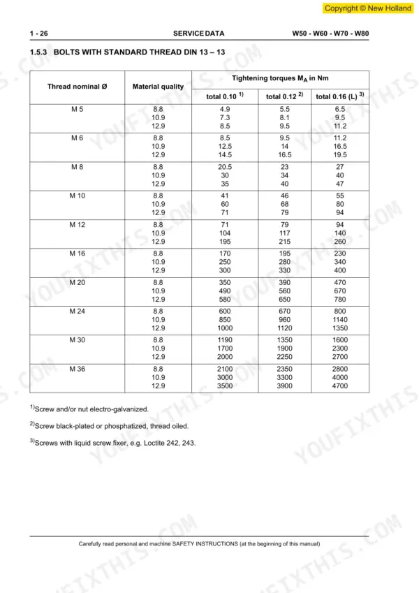
The tightening torque for the fastening bolts of the variable displacement pump / motor on New Holland W50, W60, W70, and W80 wheel loaders is 250 Nm. These bolts are M 16 / 10.9 / SW 14 and are secured with a liquid locking agent. p. 63
What is the diesel engine oil capacity (including filters) for the New Holland W50 wheel loader?
The diesel engine oil capacity, including filters, for the New Holland W50 wheel loader is 10.5 liters. The oil should be changed every 1000 operating hours or as specified in the operating instructions. p. 60
What is the front axle differential oil capacity for the New Holland W50 wheel loader?
The front axle differential oil capacity for the New Holland W50 wheel loader is 7.5 liters. The oil should be API GL4, GL5, or MIL-L2105/2105D and changed after 1000 operating hours or 3 years at the latest. p. 60
What is the tightening torque for the wheel nuts on New Holland W50, W60, W70, and W80 wheel loaders?
The tightening torque for the wheel nuts (A 20-8, M 20 x 1.5 / SW 27) on New Holland W50, W60, W70, and W80 wheel loaders is 500 Nm. This is a critical torque specification for wheel assembly. p. 63
What do I get after purchasing this New Holland W50 & variants manual?
This is a 452-page searchable PDF ready for immediate download. Works on any device, so pull it up on your phone while you're under the hood. No shipping, no waiting.
Am I able to print pages from this New Holland W50 & variants manual?
Absolutely. No DRM or copy protection. Print the whole manual or just the pages you need. Any home or office printer works.
Does this New Holland W50 & variants Workshop Manual cover the hydraulic system?
Included. Hydraulic system schematics cover all circuits, control valves, and component specifications for the New Holland W50 & variants.






Reviews
There are no reviews yet.