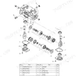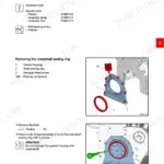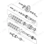
Part of the Yanmar Repair Manuals.
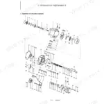
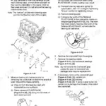
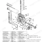
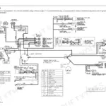
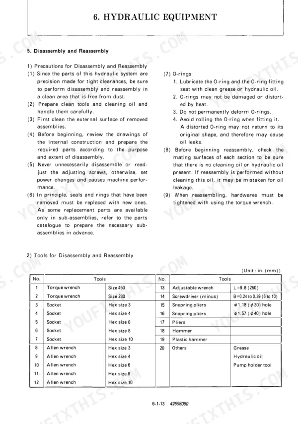
Trace a fault on a Yanmar B50-2B from the pilot valve to the travel motor and you need a document that walks the whole excavator end to end. This service manual covers measurement and adjustment on the 4TNE88B-1 diesel, the fuel supply and electrical systems, hydraulic circuit operation and pressure adjustment, and full teardown procedures for the hydraulic pump, control valve, pilot valve, swing motor and travel motor.
Most people who buy it work on the machine alone, with no dealer tech to ask. Servicing standards, torque tables and a symptom-based troubleshooting chapter mean you are not guessing at clearances or relief settings while a crew waits on the machine.
It applies to the US-spec B50-2B from serial number 65001 onward: 425 pages, Yanmar publication 42698080, delivered as a PDF. Keep it on the laptop in the truck or print the pages you need; it goes wherever the machine is.
What's Inside This Yanmar B50-2B (US) Manual
| System | Pages | Key Topics |
|---|---|---|
| General Cautions for Maintenance Work | 6-14 | 1-1 Correct Work, 1-2 Safety Precautions, 1-3 Preparations, 1-4 Cautions for Disassembly and Reassembly, 1-5 Cautions for Attaching and Detaching Hydraulic Equipment |
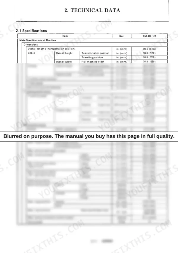
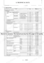
| Technical Data | 15-26 | 2-1 Specifications, 2-2 External Drawings and Working Ranges, 2-3 Weight of Main Parts, 2-4 Lifting Capacities |
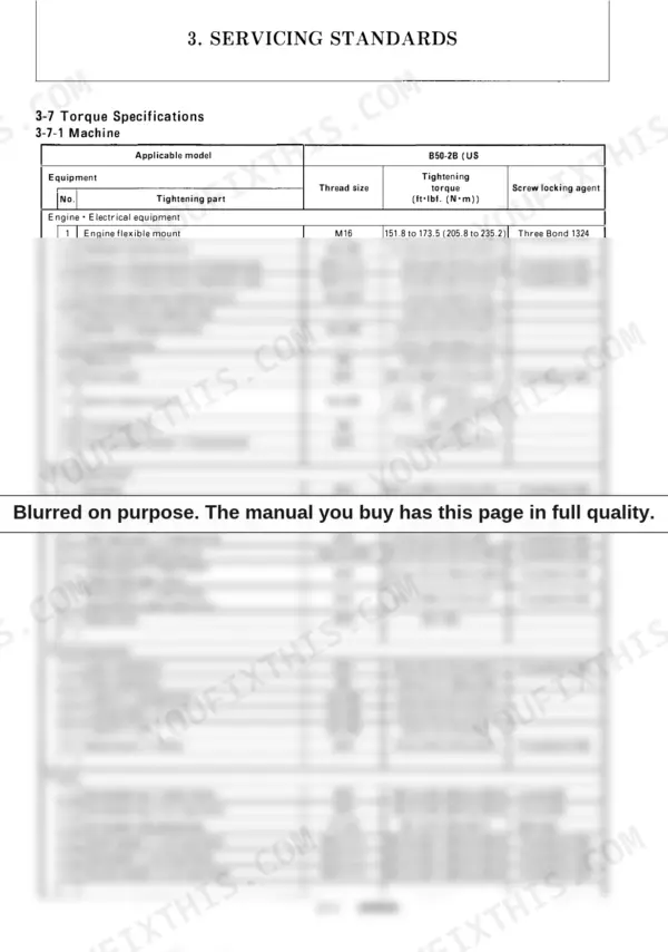
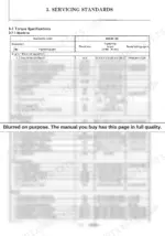
| Servicing Standards | 27-45 | 3-1 Machine Performance, 3-2 Engine, 3-3 Undercarriage, 3-4 Control Devices, 3-5 Hydraulic Equipment, 3-6 Work Implement, 3-7 Torque Specifications |
| Engine | 46-105 | 4-1 Measurement, Inspection and Adjustment, 4-2 Measuring Process, Service Data and Corrective Action, 4-3 Precautions Reassembly, 4-4 Fuel Supply System, 4-5 Electrical Equipment |
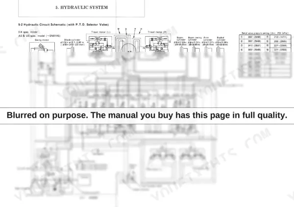
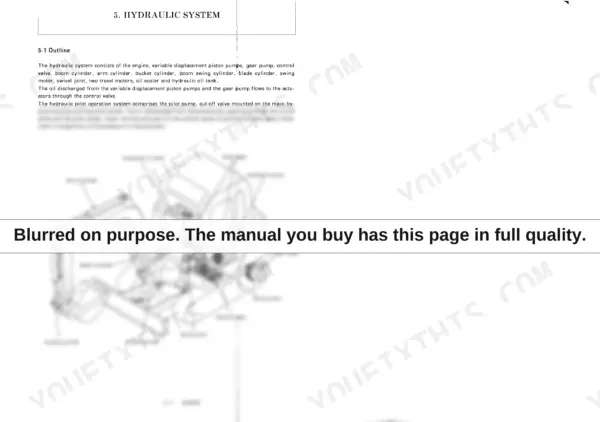
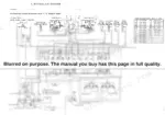
| Hydraulic System | 106-149 | 5-1 Outline, 5-2 Hydraulic Circuit Schematic(with P.T.O. Selector Valve), 5-3 Circuit Operation, 5-4 Pressure Adjustment |
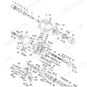
| 6-1 Hydraulic Pump | 151-183 | Hydraulic Pump, Valve Assembly, Pilot Oil Relief Valve, Oil Intake Port, Pilot Oil Discharge Port, Valve Ass'y, Solenoid Valve, Disc Filter |
| 6-2 Control Valve | 184-228 | Control Valve, Right Valve Group, Center Valve Group, Left Valve Group, Bucket, Boom, Travel (R), Inlet |
| 6-3 Pilot Valve | 229-255 | Pilot Valve, Pressure Reducing Valve Section, Handle Section, Port Plate, Spool, Handle, Push Rod, Joint |
| 6-4 Swing Motor | 256-285 | Swing Motor, Hydraulic Motor, Mechanical Brake, Check Valve, Relief Valve, Reduction Gear |
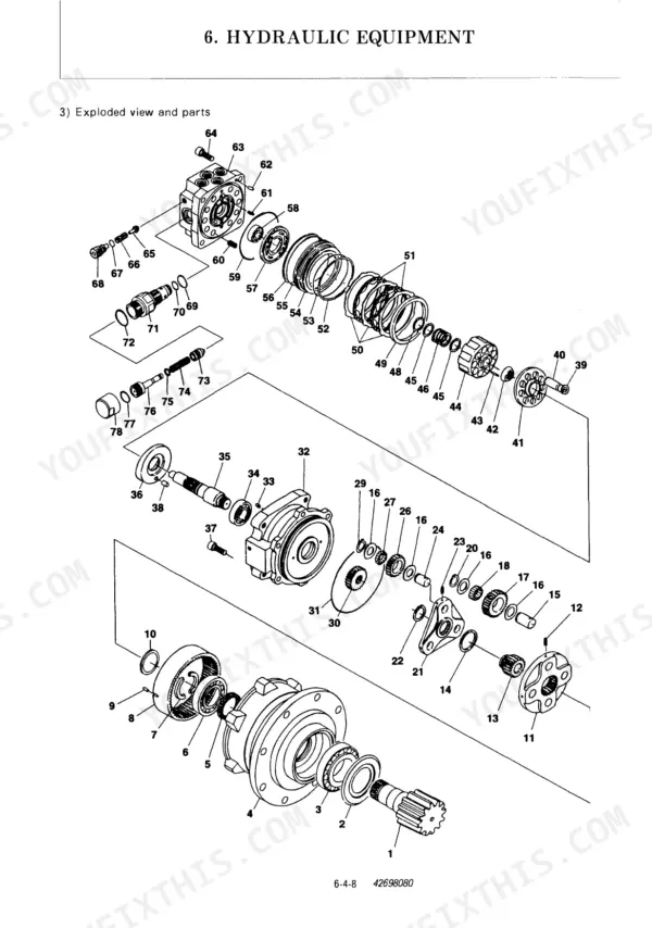
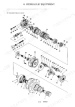
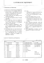
| 6-5 Travel Motor | 286-328 | Travel Motor, Hydraulic Equipment, Counter-Balance Valve, Relief Valve, Two-Speed Switch Mechanism, Reduction Gear, Exploded View and List of Parts, Special Tools |
| Adjustment Procedures for Each Equipment | 329-380 | 7-1 Electeic Equipment of the Machine, 7-2 Undercarriage, 7-3 Controls, 7-4 Swing System |
| Periodic Inspection and Servicing | 381-383 | List of Periodic Inspection and Servicing |
| Fuel,Lube Oil and Grease Recommended | 384-386 | 9-1 Fuel, Lube Oil and Grease Recommended by Yanmar, 9-2 Cooling Water Recommended by Yanmar |
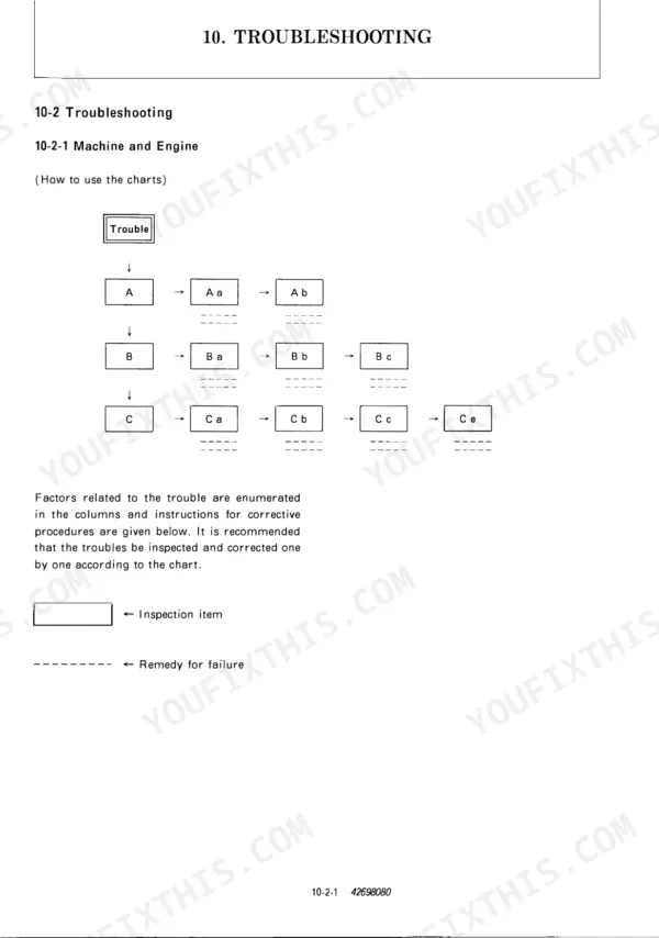
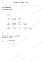
| Troubleshooting | 387-425 | 10-1 Non-Breakdowns, 10-2 Troubleshooting, Reference Data |
Quick Reference Specifications
| Specification | Value | Page |
|---|---|---|
| Fuel injection nozzle injection pressure | 2844 to 2986 PSI (19614 to 20595 kPa) | p. 22 |
| Fuel injection nozzle injection hole dia. X no. of holes | φ0.009 (φ0.23) X 4 in. (mm) | p. 22 |
| FO filter filtration area | 139.5 (900) sq.in. (sq.cm) | p. 21 |
| Fuel filter element replacement interval | Every 250 hrs | p. 382 |
| Oil/water separator type | Mesh filter | p. 21 |
| Oil/water separator cleaning interval | Every 200 hrs | p. 383 |
| LO filter filtration area | 155 (1000) sq.in. (sq.cm) | p. 21 |
| Engine oil filter element replacement interval | Every 400 hrs | p. 383 |
| Air cleaner type | Cyclone type | p. 21 |
| Air cleaner filtration area | 11.84 (1.1) sq.ft. (sq.m) | p. 21 |
| Fan belt size | A37 | p. 21 |
| V-belt deflection | 0.39 to 0.59 in. (10 to 15mm) | p. 50 |