

Part of the Yanmar Repair Manuals.
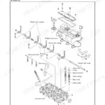
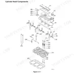
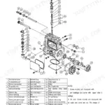
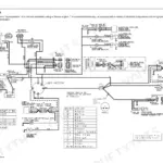
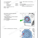
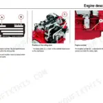
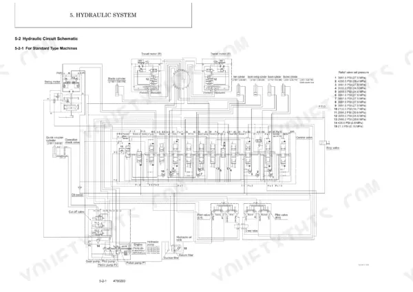
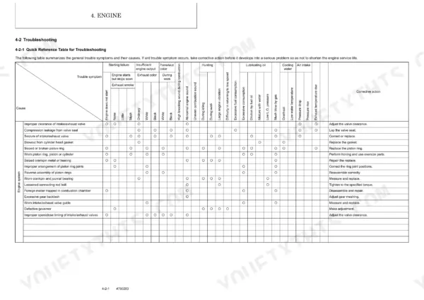
Need the factory specs for your Yanmar ViO75-A excavator? This 584-page Yanmar ViO75-A service manual PDF (OEM #0BKB3-G75000) puts the complete factory repair data in front of you: engine, hydraulic system, hydraulic components, undercarriage, and electrical circuits. Inside: hydraulic schematics with full fluid routing and pressure adjustment procedures for both piston pumps, wiring diagrams covering every machine circuit, and a troubleshooting section walking engine and hydraulic faults from symptom to fix. Step-by-step rebuild procedures cover the control valve, swing motor, travel motor, and hydraulic pump in sequence. Set each system relief valve to 3555 PSI (24.5 MPa) at 18.5 GPM (70 L/min); torque your track roller bolts to 274.9 to 296.6 ft·lbf (372.7 to 402.1 N·m). Your machine is down. Bookmarked and keyword-searchable: open it on any device and get back to digging.
Complete the set for your ViO75-A
- Parts Catalog: Yanmar ViO75-A Parts Catalog (Excavator)
What's Inside This Manual
| System | Pages | Key Topics |
|---|---|---|
| General Cautions for Maintenance Work | 11-24 | 1-1 Correct Work, 1-2 Safety Precautions, 1-3 Preparations, 1-4 Cautions for Disassembly and Reassembly, 1-5 Cautions for Removal and Installation of Hydraulic Equipment |
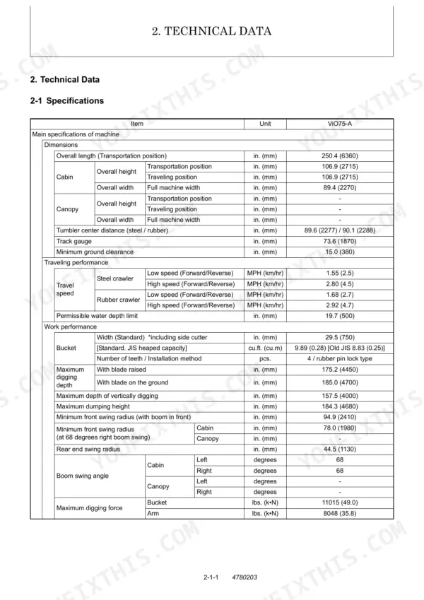
| Technical Data | 25-38 | 2-1 Specifications, 2-2 Outline Drawing and Working Area, 2-3 Weight List of Main Parts, 2-4 Lifting Capacity List |
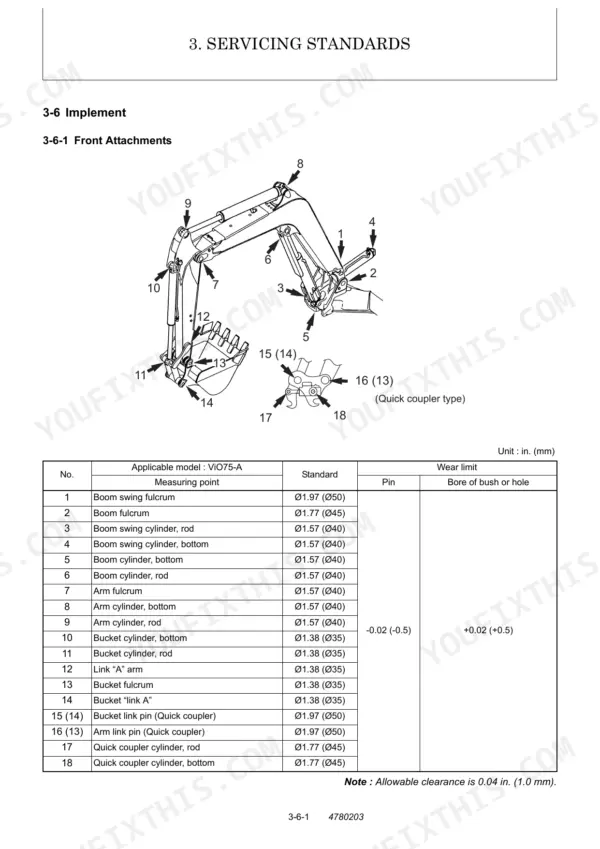
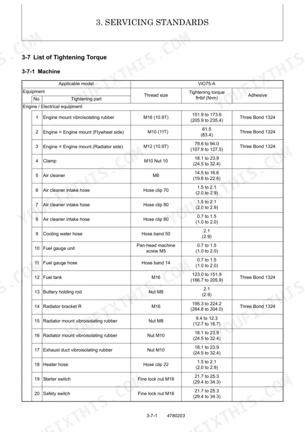
| Service Standards | 39-60 | 3-1 Machine Performance, 3-2 Engine, 3-3 Undercarriage, 3-4 Controls, 3-5 Hydraulic Equipment, 3-6 Implement, 3-7 List of Tightening Torque |
| Engine | 61-140 | 4-1 General, 4-2 Troubleshooting, 4-3 Inspection and Adjustment, 4-4 Engine Body, 4-5 Lubrication System, 4-6 Cooling System, 4-7 Fuel Injection Pump / Governor, 4-8 Starting Motor |
| Hydraulic System | 141-184 | 5-1 Outline, 5-2 Hydraulic Circuit Schematic, 5-3 Circuit Operation, 5-4 Pressure Adjustment |
| Hydraulic Equipment | 185-410 | 6-1 Hydraulic Pump, 6-2 Control Valve, 6-3 Pilot Valve, 6-4 Swing Motor, 6-5 Travel Motor, 6-6 Pilot Check Valve |
| Adjustment and Repair | 411-532 | 7-1 Electric Equipment of the Machine, 7-2 Undercarriage, 7-3 Controls, 7-4 Swing Bearing, 7-5 Hydraulic Equipment, 7-6 Implement, 7-7 Cabin, 7-8 Air Conditioner |
| Periodic Inspection and Servicing | 533-536 | 8-1 List of Periodic Inspection and Servicing |
| Fuel, Lube Oil and Grease Recommended | 537-540 | Fuel, Lube Oil, Grease, Antifreeze, Hydraulic Oil, Cooling Water Mixture Ratio |
| Troubleshooting | 541-578 | 10-1 Non-Breakdowns, 10-2 Troubleshooting |
| Reference Data | 579-582 | 11-1 Specifications for Attachment |
Quick Reference Specifications
| Specification | Value | Page |
|---|---|---|
| Sprocket installation bolt torque | 137.4 to 151.9 ft·lbf (186.3 to 205.9 N·m) | p. 442 |
| Track roller installation bolt torque | 274.9 to 296.6 ft·lbf (372.7 to 402.1 N·m) | p. 450 |
| System relief valve (Piston pump P1) set pressure | 3555.0 PSI (24.5 MPa) at 18.5 GPM (70 L/min) | p. 181 |
| System relief valve (Piston pump P2) set pressure | 3555.0 PSI (24.5 MPa) at 18.5 GPM (70 L/min) | p. 181 |
| Water separator cleaning interval | Every 100 hours | p. 93 |
| Suction filter type | Wire gauze | p. 30 |
| Suction filter filtration area | 338 sq.in. (2180 sq.cm) | p. 30 |
| Engine oil recommended type | SAE10W30, CD class | p. 539 |
| Engine oil capacity | 10.78 Qts. (10.2 L) | p. 539 |
| Track roller quantity (one side) | 5 pcs. | p. 31 |
| Idler quantity (one side) | 1 pcs. | p. 29 |
| Cooling water system issue | Low cooling water level, remedy: Supply | p. 93 |