
Part of the Case Repair Manuals.
You are about to tee a gauge into the loader valve or unbolt the SCR catalyst on an 821F or 921F. This is Case service manual 84487565, 1st edition, April 2011, for the Tier 4 wheel loaders.
Tracing an SCR code or a weak lift circuit without specs is how a half-day job turns into a week. This book has the pressure test points, the fault code tables, the removal steps and the fold-out electrical and hydraulic schematics for both models.
Print it. You can take the pages to the bench, get hydraulic oil on them and still read the wheel bolt torque off page 794.
What's Inside This Case 821F, 921F Repair Manual
| System | Pages | Key Topics |
|---|---|---|
| Specifications, Fluids and Lubricants | 1-23 | General Torque Specifications, Capacities and Lubricants for 821F and 921F, SCR Overview, Maintenance Schedule, Metric Conversion Chart |
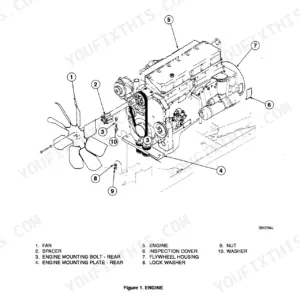
| Engine Removal, Stall Test and Aftercooler | 24-63 | Engine Removal and Installation, Radiator Removal and Installation, Stall Tests, Aftercooler Troubleshooting and Leak Test |
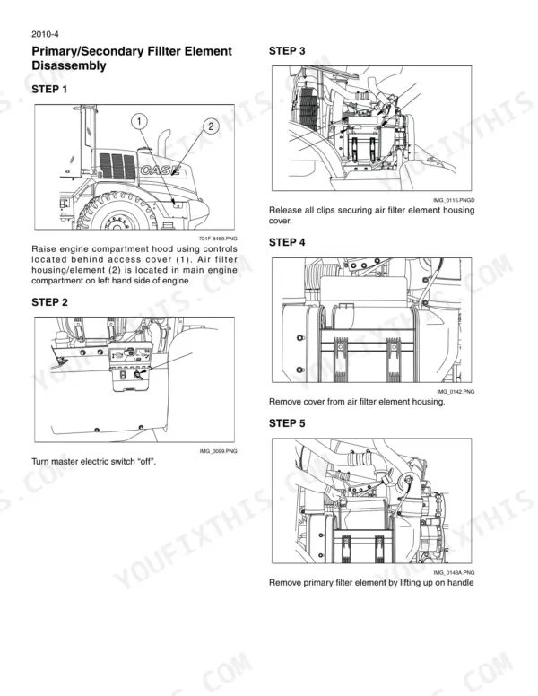
| Air Intake, SCR Sensors and Catalyst | 64-87 | Intake Air Filtration, Exhaust Temperature Sensors, NOx Sensor, SCR Catalyst Removal and Installation |
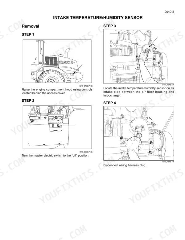
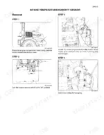
| DEF/AdBlue System | 88-137 | Intake Temperature and Humidity Sensor, DEF Heater Control Valve, DNOx Supply Module, Dosing Injector, Supply Tank and Level Sensor, DEF Filters |
| Starter and Alternator | 138-145 | Starter Removal and Installation, Alternator Removal and Installation, Belt Installation |
| Electrical Specifications, Troubleshooting and Schematics | 146-357 | Electrical Wire Identification, Troubleshooting Tables, Connector List, Circuit Schematics From Power Distribution to HVAC |
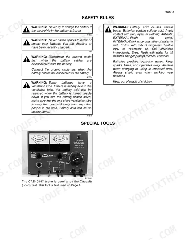
| Batteries and Jump Post | 358-369 | Battery Maintenance, Battery Test, Jump Post Option |
| Instrument Cluster and Fault Codes | 370-445 | Retrieving Fault Codes, Engine Fault Codes, Transmission Fault Codes, SCR Fault Codes, Gearbox Calibration |
| Steering System | 446-495 | Steering Control Valve, Auxiliary Steering Priority Valve, Steering Pressure Checks and Troubleshooting, Steering Cylinders, Center Pivot, Auxiliary Steering Motor and Pump |
| Joystick Steering System | 496-543 | JSS Description, PVFC and PVG32 Valves, JSS Wiring Diagram, JSS Hydraulic Components |
| Power Train Removal and Transmission Checks | 544-589 | Transmission and Axle Removal, Transmission Operation, Clutch Calibration, Pressure Test Points |
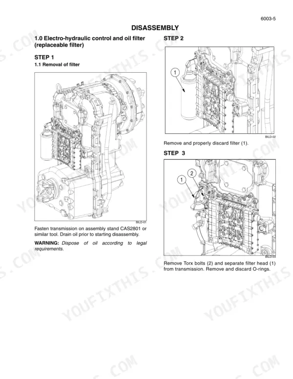
| 4 and 5 Speed Transmission | 590-679 | Transmission Disassembly, Transmission Reassembly |
| Multitrac Axles | 680-777 | MT-L 3085 II and 3095 II Axles, MT-L 3105 II Axle, Gear Tooth Contact Patterns, Output and Brake, Multi-Disk Differential |
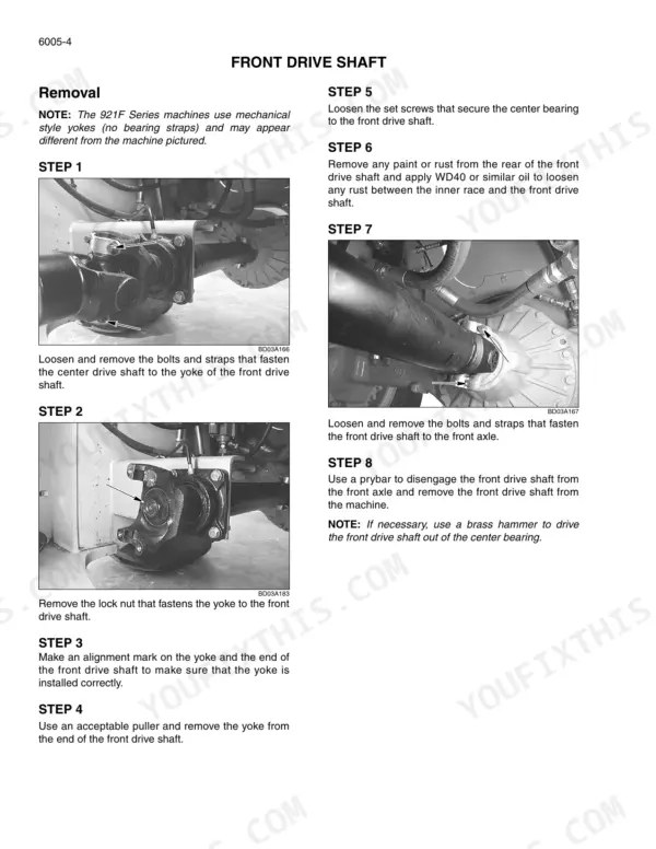
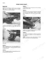
| Drive Shafts, Wheels and Tires | 778-795 | Front Drive Shaft, Center Bearing, Universal Joints, Tire Pressures, Installing a Wheel |
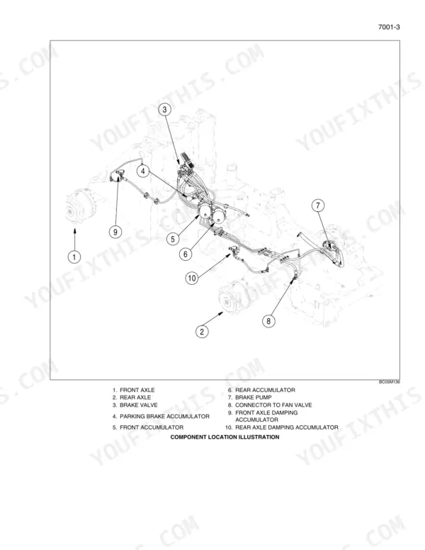
| Brakes | 796-831 | Brake Valve, Brake Accumulators, Brake Pump, Brake Troubleshooting and Bleeding, Modulation Pressure Check, Parking Brake Test |
| Hydraulic Component Removal | 832-863 | Loader Control Valve, Remote Control Valve, Lift Cylinders, Z-Bar Bucket Cylinder |
| Hydraulic Specifications, Pressure Checks and Cleaning | 864-897 | Pump Differential Pressure, Loader Limit Pressure, Circuit Relief Valves, Cleaning the Hydraulic System, Flushing Water From the System |
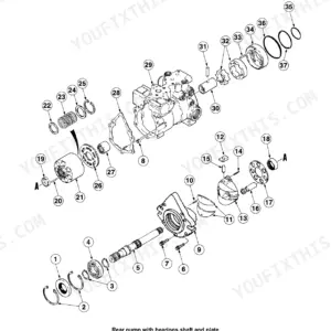
| Hydraulic Pump, Valves, Cylinders and Ride Control | 898-959 | Hydraulic Pump Overhaul, Loader Control Valve Overhaul, Lift and Bucket Cylinders, Coupler Solenoid Locking Valve, Ride Control Accumulator and Valve |
| Air Conditioning and Heater | 960-1017 | HFC-134a Troubleshooting and System Checks, Refrigerant Recovery, Evacuation and Recharging, Compressor, Heater Valve and Blowers |
| Loader, ROPS, Cab Glass and Camera | 1018-1057 | Bucket Teeth, Return to Dig Adjustment, Loader Frame Removal, ROPS Canopy and CSF Cab, Cab Glass Installation, Rear View Camera |
| Electrical and Hydraulic Schematics | 1058-1063 | Electrical Schematic Sides 1 to 4, 821F Hydraulic Schematic, 921F Hydraulic Schematic |
Quick Reference Specifications
| Specification | Value | Page |
|---|---|---|
| Service manual | Part number 84487565, 1st edition, April 2011 | p. 1 |
| Fuel tank | 288 liters (76 U.S. Gallons) | p. 10 |
| DEF tank | 41.3 liters (43.6 U.S. Quarts) | p. 10 |
| Engine oil with filter change | 13.25 liters (14 U.S. Quarts) | p. 11 |
| Engine oil, total system | 15.1 liters (16 U.S. Quarts) | p. 10 |
| Engine cooling system | 30 liters (32 U.S. Quarts) | p. 10 |
| Hydraulic reservoir refill / total system, 821F | 90.8 liters (24.0 U.S. Gallons) / 178 liters (47.0 U.S. Gallons) | p. 10 |
| Hydraulic reservoir refill / total system, 921F | 110 liters (29.0 U.S. Gallons) / 200 liters (53.0 U.S. Gallons) | p. 11 |
| Transmission refill with filter change | 34.1 liters (36 U.S. Quarts) | p. 10 |
| Axles, 821F front and rear | 40.0 liters (42.3 U.S. Quarts) each | p. 10 |
| Axles, 921F front / rear | 42.0 liters (44.4 U.S. Quarts) / 40.0 liters (42.3 U.S. Quarts) | p. 11 |
| Main relief valve | 248 to 255 bar (3600 to 3700 psi) | p. 866 |
| Transmission | 4 speed: 4 forward and 3 reverse; 5 speed: 5 forward and 3 reverse | p. 578 |
| Torque converter | Single stage, one locking unit | p. 578 |
| Axles, section 6004 | Multitrac MT-L 3085 II / 3095 II | p. 680 |
| Wheel bolts, initial / final torque | 278 Nm (205 lb ft.) / 640 - 720 Nm (475 - 530 lb ft.) | p. 794 |
| Tire options | 23.5 x 25 12 ply L2 / L3; 23.5R25 L2; 23.5R25 Radial L3 | p. 794 |
| Transmission input shaft bolts | 115 Nm (85 pound feet) | p. 593 |
| Coupler to flywheel bolts | 53 to 62 Nm (39 to 46 pound feet) | p. 780 |
Case 821F, 921F Common Problems This Manual Covers
Lift arms feel weak or slow under a full bucket
Begin in Hydraulic Specifications, Pressure Checks and Cleaning. Check pump differential pressure, loader limit pressure and the circuit relief valves against the 248 to 255 bar main relief spec. Only then pull the pump or loader control valve for overhaul.
Manual Section: Hydraulic Specifications, Pressure Checks and Cleaning p. 866SCR fault code on the cluster with DEF in the tank
Pull the code using the retrieval procedure, then look it up in the SCR fault code table. Go to the DEF/AdBlue System section to test or replace the heater control valve, DNOx supply module, dosing injector, level sensor or DEF filters.
Manual Section: Instrument Cluster and Fault Codes p. 423Slow steering or loader wandering through the articulation joint
The Steering System section covers steering pressure checks and troubleshooting, and the steering control valve and auxiliary steering priority valve. The steering limit pressure test is on page 877. If the pressures check out, inspect the steering cylinders and the center pivot.
Manual Section: Steering System p. 466Brake pedal goes soft or the loader is slow to stop
The Brakes section has brake troubleshooting, bleeding and the modulation pressure check. Check the accumulator nitrogen charge before you replace the brake valve or brake pump. Run the parking brake test before the machine goes back to work.
Manual Section: Brakes p. 809Frequently Asked Questions
Does this manual include the electrical and hydraulic schematics for the 821F and 921F?
Yes. Circuit schematics on p.345-355 run from power distribution and engine control through transmission controls, machine controls, hood lift and HVAC. The fold-out electrical schematic, sides 1 to 4, is on p.1058-1061. It is titled for the 721F, 821F and 921F, but the book only covers the 821F and 921F. The hydraulic schematics are on p.1062 (821F) and p.1063 (921F). The joystick steering wiring diagram is on p.513. p. 1058
Can I read and look up fault codes on the instrument cluster with it?
Yes. The procedure for pulling codes off the instrument cluster starts on p.387. The engine fault code tables start on p.392, transmission on p.412 and SCR on p.423. P.192 explains how to read the electrical troubleshooting tables. Gearbox calibration from the cluster is on p.385. p. 387
Does it cover the Tier 4 SCR and DEF/AdBlue system?
It does, part by part. P.14 explains how SCR works, and the exhaust temperature and NOx sensors are on p.70-79. Catalyst removal is on p.82 and installation on p.85. On the DEF side you get the heater control valve (p.94), DNOx supply module (p.100), dosing injector (p.108), supply tank (p.114), level sensor (p.122) and filters (p.128). The book has no DPF procedure. p. 14
How do I check and adjust the loader hydraulic pressures?
Start with the specifications for your model: p.866 for the 821F, p.867 for the 921F. Main relief is 248 to 255 bar (3600 to 3700 psi). High and low pump pressure tests are on p.871 and p.873. Loader limit pressure is on p.875, steering limit on p.877, loader pump cutoff on p.879 and circuit relief valves on p.884. p. 866
Does it cover the transmission rebuild and clutch calibration?
Yes. Transmission operation starts on p.576. The 4 speed has 4 forward and 3 reverse gears, and the 5 speed has 5 forward and 3 reverse. Clutch calibration for the 4-speed is on p.578, and the pressure test points are on p.581. Disassembly starts on p.594 and reassembly on p.624. Input shaft bolts take 115 Nm (85 pound feet) (page 593). p. 578









Reviews
There are no reviews yet.