Part of the Case IH Repair Manuals.
Torque values, service limits and ECU pin assignments for eight variants of the Case IH F3BFE613 engine are settled in one 252-page document, OEM part number 84473731. Sold as the Case IH F3BFE613A*A001 service manual PDF, it pairs ECU pin out and connector identification with sensing system component diagrams for the flywheel and camshaft speed sensors. Engine service work runs from top dead center and the timing gear train through crankshaft, cylinder block and cylinder head; fuel injection, turbocharger, cooling, lubrication and starting systems follow. Expect 0.6 to 2.4 V from the coolant temperature sensor between 60 and 90 °C, and set the oil filter to 35 to 40 Nm (25.8 to 29.5 lb ft). Refitting a cylinder head? Your bolt sequence runs 60 Nm, 120 Nm, then 120° and a final 60°. Bookmarks and a live text layer take you straight to the service limits or that four-stage head torque sequence in seconds.
What's Inside This Manual
| System | Pages | Key Topics |
|---|---|---|
| Service Manual | 1 | Engine |
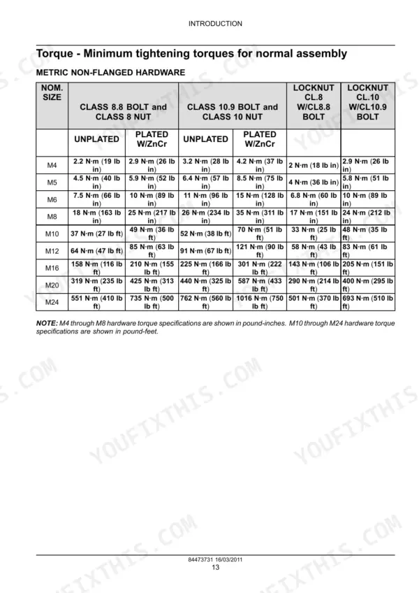
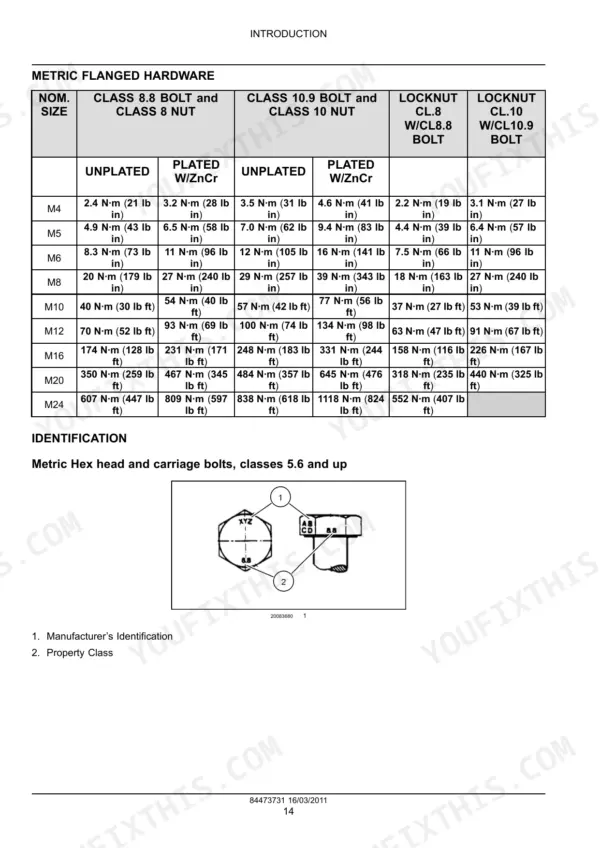
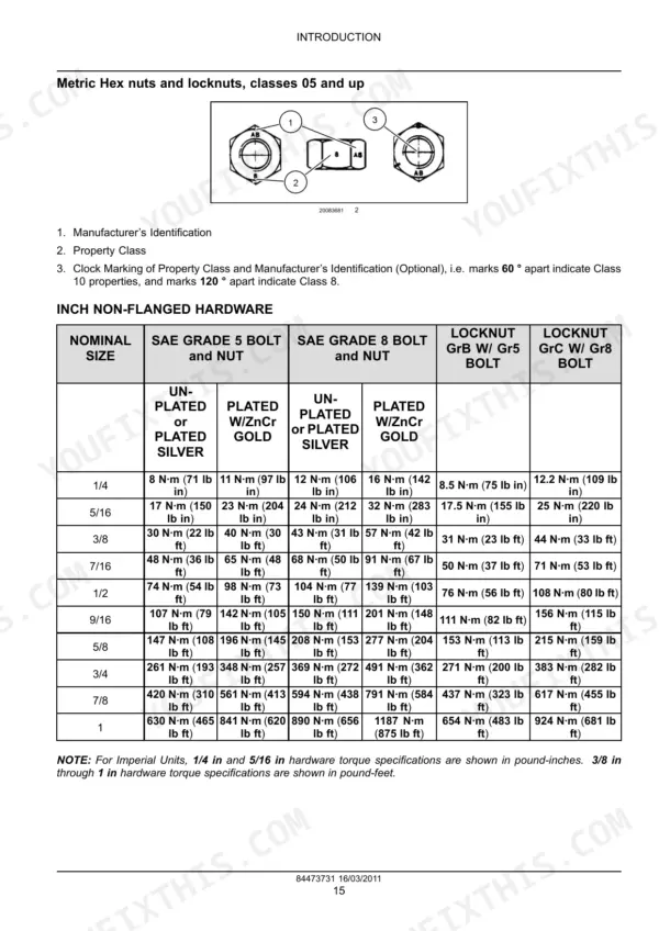
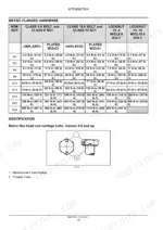
| Introduction | 3-20 | Ecology and the Environment, Safety Rules, Equipment Servicing, Navigate Through This Manual, Shop and Assembly, Tightening Torques |
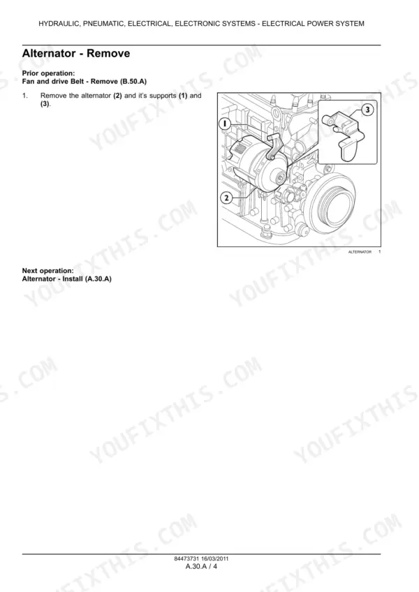
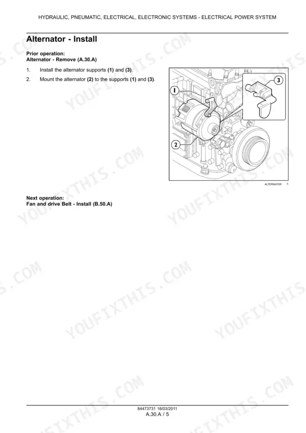
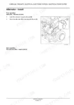
| Hydraulic Pneumatic Electrical Electronic Systems | 21-26 | Electrical Power System |
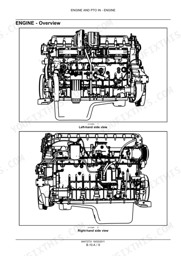
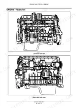
| Engine General Information and Specifications | 27-37 | Engine Specifications, Service Limits, Engine Overview, Engine Views |
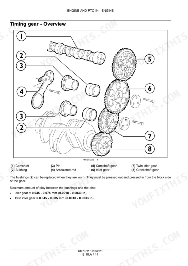
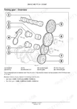
| Valve Drive and Timing Gear | 38-42 | Rocker Assembly, Rocker Shaft, Timing Gear Overview, Idler Gear, Twin Idler Gear |
| Connecting Rod, Piston, and Flywheel | 43-45 | Connecting Rod and Piston Overview, Connecting Rod Markings, Flywheel Overview |
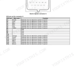
| Electronic Control Module | 46-53 | System Functions, Fuel Dosing, Injection Lead Control, ECU Pin Out, Connector Identification |
| Sensing System | 54-58 | Component Diagram, Flywheel Speed Sensor, Camshaft Speed Sensor, Sensing System Overview |
| Engine Service and Maintenance | 59-158 | Engine Stand, Top Dead Center, Camshaft Gear, Rocker Assembly, Crankshaft, Cylinder Block, Cylinder Head, Valve Cover |
| Fuel and Injection System | 159-176 | Fuel System Overview, Regulator Valve, Fuel Injector, Fuel Transfer Pump, Sensing System |
| Air Intake, Exhaust, Cooling, Lubrication, and Starting Systems | 177-248 | Turbocharger, Air Intake Manifold, Exhaust Manifold, Engine Coolant System, Lubrication System, Starting System |
Quick Reference Specifications
| Specification | Value | Page |
|---|---|---|
| Pump injector adjusting screw torque | 5 Nm (44.3 lb in) | p. 73 |
| Cylinder head bolt torque | Stage 1: 60 Nm (44.3 lb ft), Stage 2: 120 Nm (88.5 lb ft), Stage 3: 120°, Stage 4: 60° | p. 138 |
| Fuel injector bracket and bolt torque | 26 Nm (19.2 lb ft) | p. 15 |
| Coolant temperature sensor voltage range at 60 - 90 °C (140 - 194 °F) | 0.6 - 2.4 V | p. 197 |
| Oil filter tightening torque | 35 - 40 Nm (25.8 - 29.5 lb ft) | p. 218 |
| Oil pressure regulator valve start of opening pressure | 5 bar (72.5 psi) | p. 220 |
| Oil cooler bypass valve start of opening pressure | 3 bar (43.5 psi) | p. 222 |
| Bore | 135 mm | p. 31 |
| Stroke | 150 mm | p. 31 |
| Displacement | 12880 cm³ | p. 31 |
| Injection pressure | 2000 bar | p. 31 |
| Alternator Voltage | 14 V | p. 23 |