Part of the Case IH Repair Manuals.
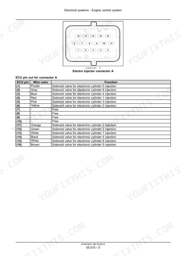
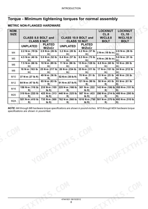
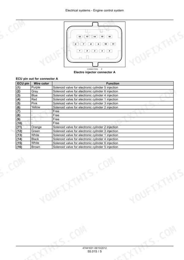
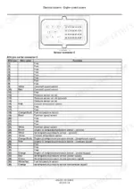
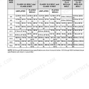
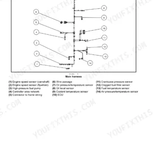
Setting top dead center and measuring cylinder liner protrusion open the 294-page Case IH F2CFA614B service manual PDF (OEM ID 47441631), which also covers the F2CFA614C engine. Wiring diagrams trace the fuel injection, engine control, starting and alternator circuits, and the minimum tightening torque tables cover metric and inch hardware, flanged and non-flanged. Rebuild chapters walk you through valve guide and seat replacement, crankshaft bearing selection and end play, piston ring measurement, camshaft timing, and common rail injection. Confirm the oil pressure control valve starts opening at 5 bar (72.5 psi), and expect each injector coil to read 0.56 to 0.57 Ω. Refitting injectors? You need 26 N·m (19 lb ft) on the mounting bolts and 33 to 37 N·m (24 to 27 lb ft) at the injector end of each high pressure pipe. The pages print cleanly as a working copy, with crankshaft end play and liner protrusion checks laid out, and bookmarks jump to each chapter.
What's Inside This Manual
| System | Pages | Key Topics |
|---|---|---|
| Safety Rules | 6 | Personal Safety, Machine Safety, Information |
| Basic Instructions - Important Notice Regarding Equipment Servicing | 7 | Repair and Maintenance, Qualified Personnel, Special Tools, CNH Sales and Service Networks |
| Basic Instructions - Shop and Assembly | 8-9 | Shimming, Rotating Shaft Seals, O-Ring Seals, Sealing Compounds, Spare Parts |
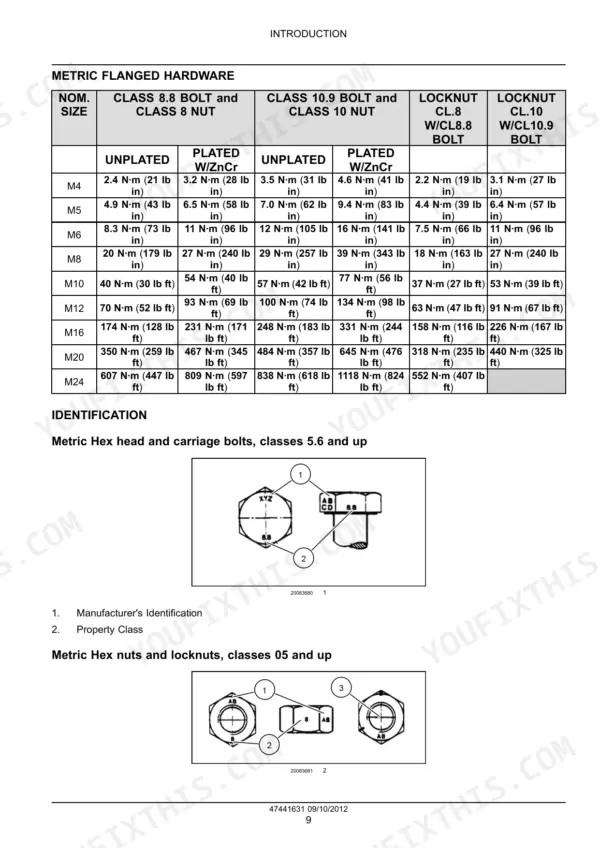
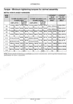
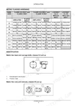
| Torque - Minimum Tightening Torques for Normal Assembly | 10-14 | Metric Non-Flanged Hardware, Metric Flanged Hardware, Inch Non-Flanged Hardware, Inch Flanged Hardware, Hardware Identification |
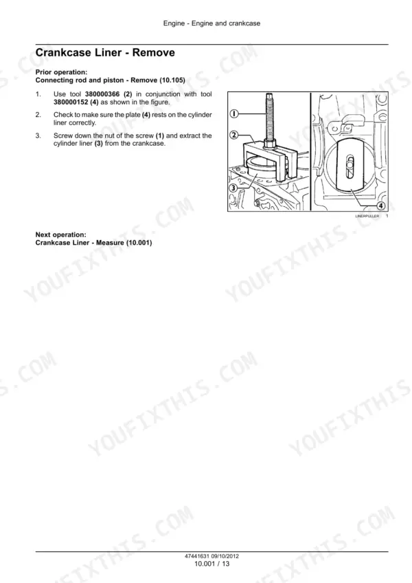
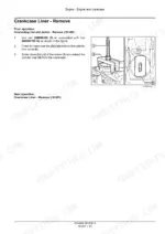
| Engine and Crankcase | 15-32 | Top Dead Center (TDC), Cylinder Liner Removal, Cylinder Liner Installation, Cylinder Liner Measurement, Liner Protrusion |
| Cylinder Heads | 33-52 | Valve Cover Removal, Cylinder Head Disassembly, Valve Cleaning, Valve Measurement, Valve Guide Replacement, Valve Seat Replacement |
| Pan and Covers | 53-64 | Engine Oil Pan Removal, Engine Oil Pan Installation, Front Engine Block Cover, Rear Engine Block Cover |
| Crankshaft and Flywheel | 65-84 | Flywheel Removal, Flywheel Installation, Crankshaft Oil Seal, Crankshaft Removal, Bearing Selection, Crankshaft End Play |
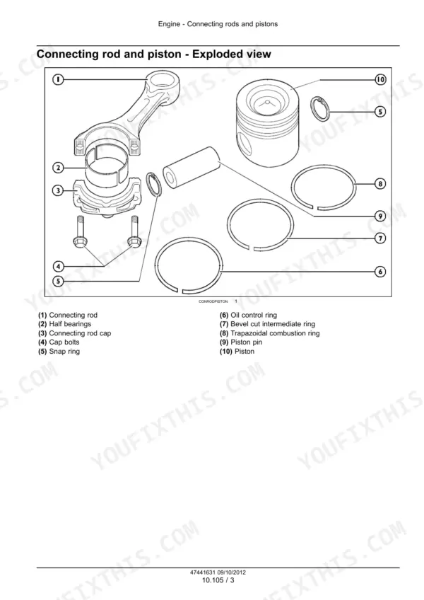
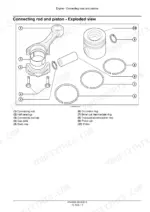
| Connecting Rods and Pistons | 85-102 | Connecting Rod Removal, Piston Disassembly, Piston Ring Measurement, Connecting Rod Alignment, Piston Pin Measurement |
| Valve Drive and Gears | 103-122 | Rocker Arm Removal, Camshaft Measurement, Camshaft Timing, Camshaft Bushing Replacement, Camshaft Gear Removal |
| Balancer and Damper, Pump Drives, Fuel Filters, Lift Pump and Lines, Fuel Injection System | 123-174 | Crankshaft Damper, Crankcase Gears, Fuel Filter Replacement, Fuel Lift Pump, High Pressure Pump, Common Rail, Fuel Injectors |
| Turbocharger and Lines, Intake and Exhaust Manifolds and Muffler, Engine Lubrication System, Engine Cooling System, Fan and Drive | 175-240 | Turbocharger Removal, Intake Manifold, Engine Oil Filter, Engine Oil Pump, Blowby Re-Circulation, Water Pump, Coolant Thermostat |
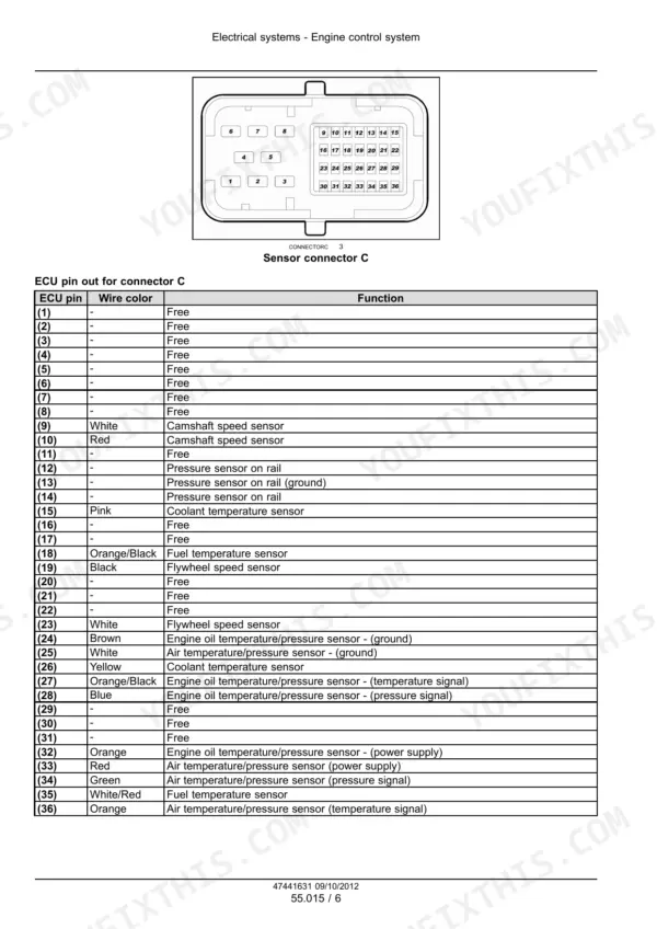
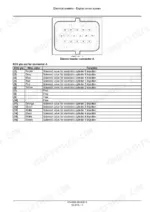
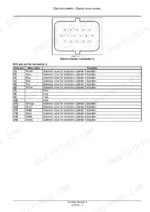
| Electrical Systems | 241-294 | Fuel Injection System, Engine Cooling System, Engine Oil System, Engine Intake and Exhaust System, Engine Control System, Engine Starting System, Alternator |
Quick Reference Specifications
| Specification | Value | Page |
|---|---|---|
| Fuel filter installation | 3/4 of a turn after seal contacts sealing surface | p. 142 |
| Resistance of each injector coil | 0.56 - 0.57 Ω | p. 163 |
| Injector mounting bolt torque | 26 N·m (19 lb ft) | p. 170 |
| Engine oil filter Bypass valve opening pressure | 3.1 - 3.7 bar (45.0 - 53.7 psi) | p. 196 |
| Oil pressure control valve start of opening pressure | 5 bar (72.5 psi) | p. 197 |
| Water pump bolt torque | 20 - 24 N·m (15 - 18 lb ft) | p. 221 |
| Thermostat opening temperature | 83 - 87 °C (181 - 189 °F) | p. 219 |
| Coolant temperature sensor resistance at -10 °C (14 °F) | 8100 - 10770 Ω | p. 249 |
| Coolant temperature sensor resistance at 20 °C (68 °F) | 2280 - 2720 Ω | p. 249 |
| Maximum torque | 6 - 10 Nm (53 - 89 lb in) | p. 273 |
| Resistance | 880 - 920 Ω | p. 273 |
| Bore | 117 mm | p. 17 |