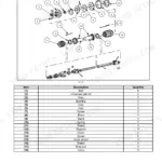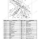
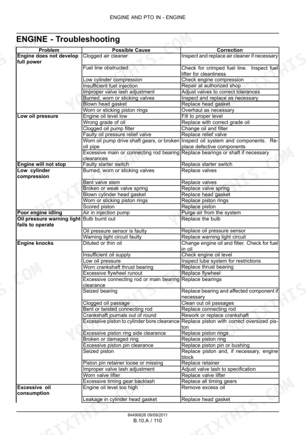
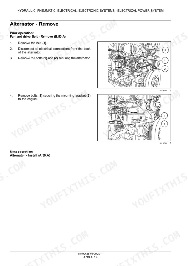
Part of the Case IH Repair Manuals.
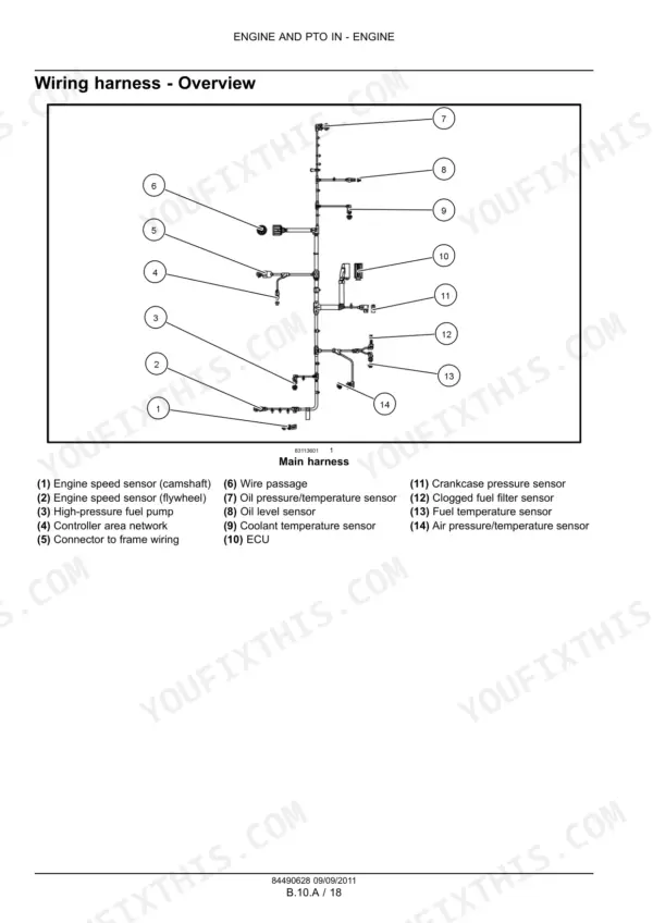
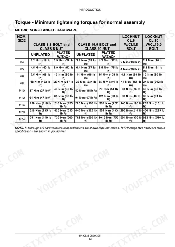
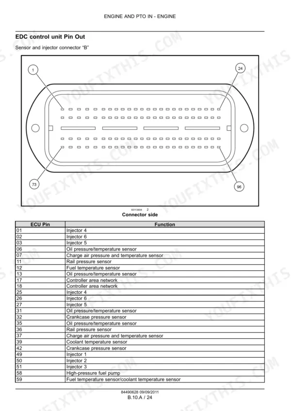
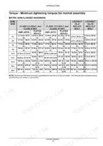
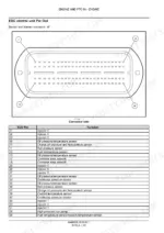
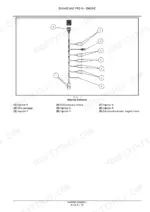
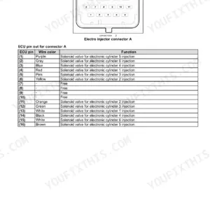
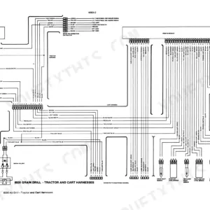
Torque values, sensor checks and component service for 12 Case IH F3D engine variants are settled in this 255-page Case IH F3DE3684A service manual PDF (OEM ID 84490628), spanning the F3DE3684, F3DFA613 and F3DFE613 builds. Wiring harness diagrams and the EDC control unit pin out let you trace the flywheel and camshaft speed sensor circuits back to the electronic control module. Separate sections then work through the high pressure common rail, injectors, turbocharger, SCR, coolant and lubrication systems, and the grid heater starting circuit. Test the camshaft speed sensor for 880 to 920 Ω, and seat the turbocharger bracket bolts at 63 to 77 N·m. Sourcing a replacement water pump, oil pump or fuel injector? Each is named in the cooling, lubrication or fuel sections. Printed, the text-based pages stay sharp as a working copy, so your service limits and minimum tightening torques can sit beside the engine while bookmarks handle the screen.
What's Inside This Manual
| System | Pages | Key Topics |
|---|---|---|
| Service Manual | 1 | Engine and PTO in |
| Introduction | 4-21 | Foreword Ecology and the Environment, Safety Rules, Basic Instructions Equipment Servicing, Basic Instructions Manual Navigation, Basic Instructions Shop and Assembly |
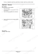
| Hydraulic Pneumatic Electrical Electronic Systems | 22-27 | Electrical Power System |
| Engine - General Information and Specifications | 28-38 | Engine Specifications, Service Limits, Engine Overview, Rocker Assembly, Timing Gear |
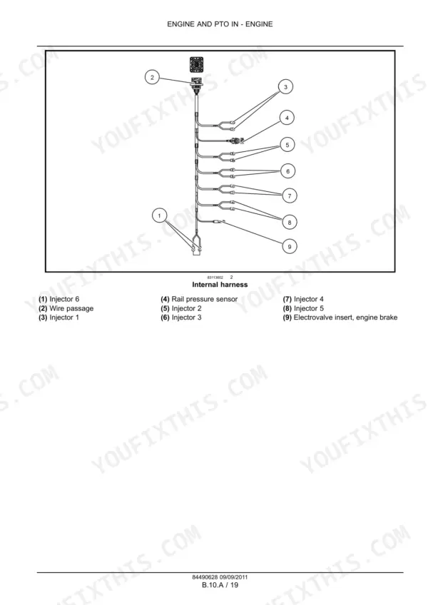
| Engine - Electronic Control and Sensing Systems | 39-57 | Electronic Control Module, Wiring Harness, Flywheel Speed Sensor, Camshaft Speed Sensor, EDC Control Unit Pin Out |
| Engine - Mechanical Service and Assembly | 58-84 | Top Dead Center, Rocker Assembly, Camshaft, Crankshaft, Cylinder Block, Cylinder Head |
| Fuel and Injection System | 85-169 | Fuel Injection Pump, Fuel Injectors, High Pressure Common Rail, Fuel Filter System, Fuel Lines |
| Air Intake and Exhaust Systems | 170-205 | Turbocharger, Air Cooler, Air Intake Manifold, Exhaust Manifold, Selective Catalytic Reduction (SCR) |
| Engine Cooling and Lubrication Systems | 206-243 | Engine Coolant System, Thermostat, Water Pump, Lubrication System, Oil Pump, Oil Filter, Oil Cooler |
| Starting System | 244-253 | Cold Start Aid, Grid Heater, Engine Starter, Wiring Diagram |
Quick Reference Specifications
| Specification | Value | Page |
|---|---|---|
| Camshaft speed sensor max. tightening torque | 8 N·m (5.9 lb ft +/- ) 2 N·m (1.5 lb ft) | p. 55 |
| Camshaft speed sensor resistance | 880 - 920 Ω | p. 55 |
| Filter tightening torque | 60 N·m (44.3 lb ft +/- ) 5 N·m (3.7 lb ft) | p. 224 |
| Turbocharger bracket bolts torque | 63 - 77 N·m (46 - 57 lb ft) | p. 179 |
| Turbocharger flywheel housing bolts torque | 45 - 55 N·m (33 - 41 lb ft) | p. 179 |
| Coolant-temperature sensor voltage at 60 - 90 °C | 0.6 - 2.4 V | p. 211 |
| Purge plug tightening torque | 5 - 8 N·m (3.7 - 5.9 lb ft) | p. 225 |
| Engine Displacement | 12880 cm³ | p. 32 |
| Thermostat Start of opening | 82 - 86 °C (180 - 187 °F) | p. 32 |
| Injector calibration pressure | 290 - 302 bar (4205 - 4379 psi) | p. 32 |
| Cylinder liner protrusion | 0.045 - 0.075 mm (0.002 - 0.003 in) | p. 32 |
| Crankshaft end play | 0.10 - 0.30 mm (0.0039 - 0.0118 in) | p. 34 |