




Part of the Case IH Repair Manuals.
Case IH SB521 through SB551 square balers, five variants in all, are the subject of this Case IH SB521–SB551 series service manual PDF: 660 pages of factory repair procedure filed under OEM number 47917637. Hydraulic schematics map the variable displacement pump, bale density circuit, and pickup lift circuit, while the tying coverage, close to half the book, carries knotter drive, needles, billhook, twine discs, and twister frame work from teardown through adjustment. PTO drive shaft, flywheel, gearbox, and clutch service opens the mechanical sections, with general specifications printed separately for each variant. Set your packer fork drive chain sag at 9 mm (3/8 in), and pull the needle yoke once vertical movement passes 0.8 mm (1/32 in). Dry hay doesn't wait while you hunt one adjustment figure. Searchable text and bookmarked sections put that number in front of you fast, so the baler ties again while the weather holds.
What's Inside This Case IH SB521–SB551 Series Manual
| System | Pages | Key Topics |
|---|---|---|
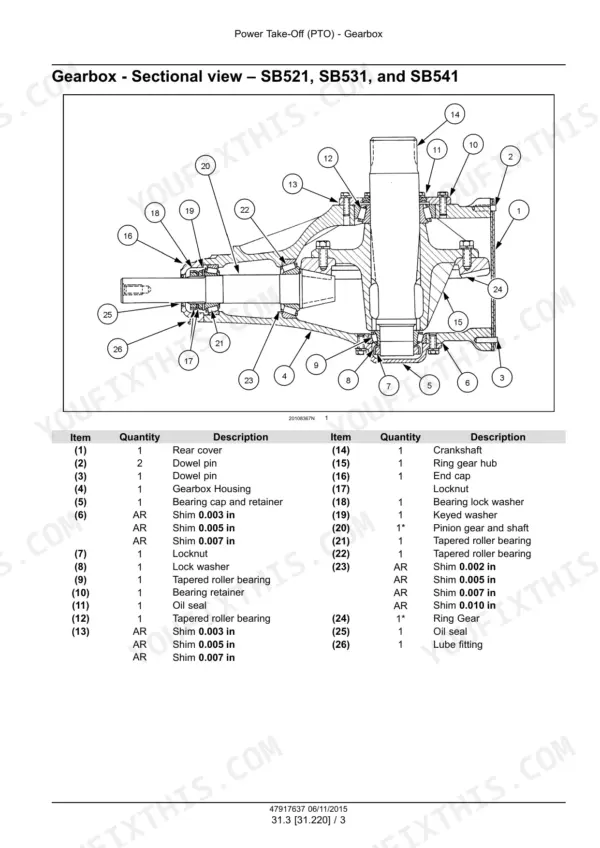
| Power Take-Off (PTO) | 42-148 | Power Take-Off (PTO) Drive Shaft, Flywheel, Gearbox, Clutches |
| Hydraulic Systems | 149-202 | Variable Displacement Pump, Bale Density Circuit, Pickup Lift Circuit, Frame Positioning Swinging |
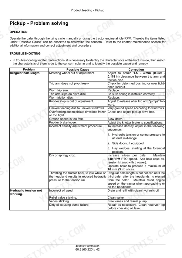
| Product Feeding | 203-296 | Feeder Housing, Feeder Drive System, Pickup, Packer, Rotor |
| Pressing - Bale Formation | 297-334 | Plunger and Connecting Rod, Bale Chamber |
| Knotter Drive System | 335-346 | Knotter Control Drive Shaft, Bearing Removal, Bearing Installation, Shaft Replacement |
| Knotter Clutch and Brake | 347-362 | Brake Adjustment, Brake Pad Removal, Brake Pad Installation, Brake Disc Replacement, Knotter Clutch Dog |
| Knotter Trip Mechanism | 363-396 | Metering Wheel, Trip Arm, Drive Gear, Bale Counter, Trip Lever, Pivot Shaft |
| Needles | 397-442 | Needle Removal, Needle Installation, Needle Yoke, Needle Protection Latch, Needle Roller Replacement |
| Knotter Stack | 443-484 | Knotter Frame, Knife Arm, Billhook, Twine Disc, Twine Finger, Knotter Stack Assembly |
| Twine Guide System | 485-504 | Twine Tension Plates, Twine Holder, Twine Guide Adjustment, Worm Shaft and Gears |
| Knotter Frame | 505-560 | Knife Arm Adjustment, Billhook Replacement, Twine Disc Cleaners, Twine Finger Lever |
| Twister Frame | 561-660 | Hook and Shaft System, Shear Plate, Shuttle Bar, Shuttle Shaft, Twist Wrapper, Wire Guides |
Quick Reference Specifications
| Specification | Value | Page |
|---|---|---|
| Hitch pin distance from tractor PTO shaft | 355 mm (14 in) | p. 48 |
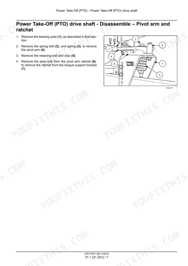
| Spring length for pivot arm and ratchet | 68 mm (2-11/16 in) | p. 50 |
| Maximum vertical movement of yoke | 0.8 mm (1/32 in) | p. 66 |
| Packer fork drive chain sag | 9 mm (3/8 in) | p. 208 |
| Rotor drive chain sag | 9 mm (3/8 in) | p. 209 |
| Sprocket teeth distance from feeder bulkhead | 29 - 31 mm (1–5/32 - 1–7/32 in) | p. 225 |
| pickup wheel flotation weight | 11 - 13 kg (24.3 - 28.7 lb) | p. 245 |
| Billhook cam spring length | 17 mm (0.67 in) | p. 479 |
| Knife arm to billhook clearance | 10 - 13 mm (0.394 - 0.512 in) | p. 479 |
| Billhook spring length | 17 mm (0.67 in) | p. 528 |
| Billhook groove pin size | 4 mm (0.16 in) | p. 529 |
| Twine holder extension (no twine) | 8 mm (0.31 in) | p. 537 |
Case IH SB521–SB551 Series Common Problems This Manual Covers
Case IH SB541 knotter missing knots, twine ends frayed, bow knots forming on random bales
Check the billhook cam spring first; compressed length should be 17 mm (0.67 in) per the chart on page 479. Verify knife arm to billhook clearance of 10 - 13 mm (0.394 - 0.512 in). Frayed twine ends usually mean a dull knife or a rough billhook horn; polish the horn and replace nicked knives.
Manual Section: Knotter Stack Troubleshooting p. 479Twine slips out of the disc before the tie cycle, loose untied loops on every few bales
Measure twine holder extension into the twine disc notch: 8 mm (0.31 in) with no twine, 3 mm (0.12 in) with twine loaded, shown on page 537. Adjust the twine holder spring until the gap reads 3 mm (0.12 in). If the disc jumps time, retorque the worm shaft nut to 34 N·m (25.1 lb ft).
Manual Section: Knotter Frame p. 537Baler plugs in heavy windrows, feeder tines stall, wads hang up at the chamber entrance
Check feeder tine bar chain deflection: 12 - 16 mm (1/2 - 5/8 in) with 45.4 kg (100.1 lb) of upward force, per page 226. Set the wooden guide gap at 3 - 6 mm (1/8 - 1/4 in) and verify packer fork drive chain sag at 9 mm (3/8 in). Then slow ground speed in the heavy stuff instead of gearing up.
Manual Section: Product Feeding p. 226Pickup bounces and skips hay on rough ground, teeth breaking faster than normal
Adjust the jam nuts on the spring rods equally until the pickup wheel carries 11 - 13 kg (24.3 - 28.7 lb), the flotation spec on page 245. A pickup riding too heavy digs in and snaps teeth. While you are under there, check pickup drive belt spring length at 283 mm - 287 mm per page 266 and replace any bent teeth.
Manual Section: Product Feeding p. 245Knotter shear bolts keep shearing, needles out of time, needle tips clipping the plunger
Shut down and recheck needle timing before you drive a needle through the plunger. Verify plunger to bale case clearance at 4 mm (0.157 in), the spec on page 480; worn plunger runners let the plunger drift into the needle slots. Inspect the needle yoke pivot pin for play, and replace shear bolts with the correct grade only, never a harder bolt.
Manual Section: Needles p. 397Frequently Asked Questions
What are the torque specifications for the knotter drive clutch nut on the SB521, SB531, SB541, SB541C, and SB551 balers?
The nut for the knotter drive clutch should be torqued to 287 N·m (212 lb ft). This procedure is detailed in the Tying/Wrapping/Twisting section of the service manual. p. 137
What is the procedure for adjusting the twine tension plates on the baler?
To adjust the twine tension plates, tighten the spring locknut until a pull force of 0.9 - 1.8 kg (2.0 - 4.0 lb) is required to pull the twine between the plates. p. 497
What is the required torque for the gearbox mounting bolts on the SB521, SB531, and SB541 balers?
The gearbox mounting bolts on these models must be tightened and torqued to 225 N·m (166 lb ft). p. 103
What is the correct plunger knife to stationary knife clearance on a Case IH SB521, SB531, SB541, SB541C, SB551 baler?
The plunger knife should be adjusted to cross the stationary knife with a clearance of 0.25 - 0.75 mm (0.010 - 0.030 in) at the three mounting bolt locations. p. 307
How do I adjust the twister hook drive chain tension?
To adjust the twister hook drive chain, tighten the jam nuts on the adjusting screw until a force of 2.3 kg (5.1 lb) deflects the chain 6 mm (1/4 in) at the midpoint between the sprockets. p. 620
What format is this Case IH SB521–SB551 Series manual in?
You get a 660-page searchable PDF that downloads instantly after checkout. Open it on your laptop, tablet, or phone, and bring it right to the shop floor.
Can I print specific sections of this Case IH SB521–SB551 Series Service Manual?
Yes. Print individual pages or full chapters for your own shop use, on letter or A4 paper.






Reviews
There are no reviews yet.