Part of the Case IH Repair Manuals.
An hour from now you could have the wobble box half out of your header with the Case IH 2042, 2052, 2062 repair manual PDF (OEM 6-14912) open beside you, all 344 pages of factory repair coverage for these draper headers. Hydraulic schematics trace the combine adapter circuits through forward, reverse, and over relief operation, while the troubleshooting section walks crop loss at the cutter bar back to the reel, drapers, or feeding. Bearing replacement, draper tensioning repair, and the complete wobble box rebuild each finish with the assembly checked and timed. Set relief pressure to the factory 137.896 bar (2000 psi), then ballast header float between 45.36 and 68.04 kg (100 to 150 pounds) for dry ground. Every hour the header sits, the crop stands. Bookmarked and text searchable, this PDF rides in the cab or the shop, wherever the header quits.
What's Inside This Repair Manual
| System | Pages | Key Topics |
|---|---|---|
| General Information | 11-12 | Standard Bolt Torque (U.S. Standard, Metric, Metric Torque for Aluminum Components) |
| Hydraulic Fittings | 13 | Steel Hydraulic Fittings |
| Product Identification Numbers | 14 | Machine Name, Model Number, Product Identification Number |
| Left Drive Shield | 15 | Tool Operated Latches, Catch Handle, Bracket |
| Lubrication and Maintenance Chart | 16 | Secondary Drive Shaft, Sickle Cutter Bar, Hydraulic Oil Level, Sickle Head, Tire Pressure, Reel Support Bushings |
| General Safety Information | 17-24 | Safety Rules, Service Area, Fire Extinguisher, First Aid Kit, Personal Safety, Combine Ballast, Transportation Safety, Tire Safety |
| Combine Feeder Safety Lock | 25 | Lift Cylinder, Latch Pin, Lift Cylinder Rod |
| Reel Safety Lock | 26 | Fire or Explosion Prevention |
| Troubleshooting | 27-42 | Crop Loss at Cutter Bar, Cutting Components, Reel, Drapers, Feeding |
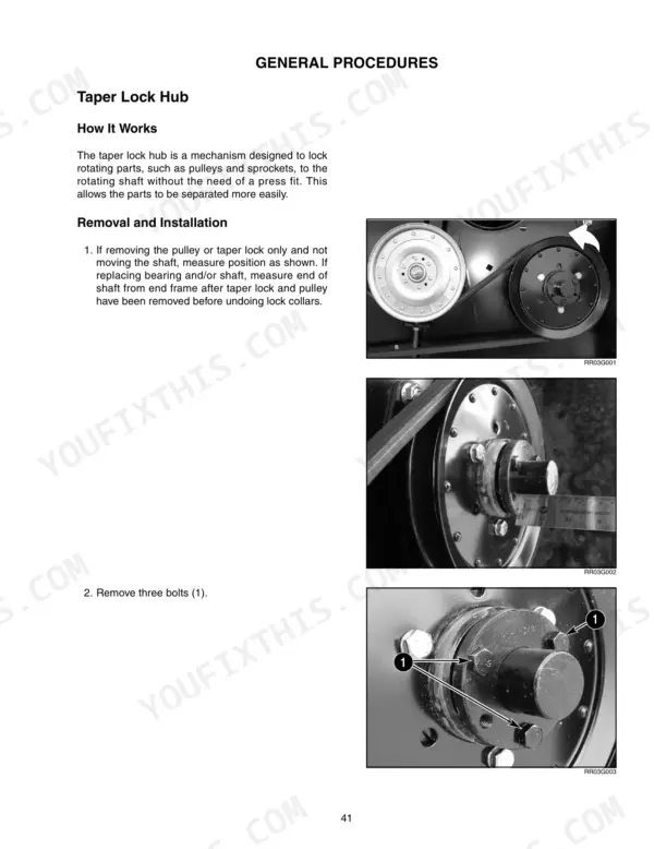
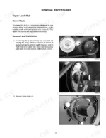
| General Procedures | 43-52 | Taper Lock Hub (How It Works, Removal and Installation), Lock Collar (How It Works, Universal Joint (How It Works, Rebuilding the Universal Joint) |
| Knife Drive System | 53-82 | Knife Drive System - How It Works, Combine Output Shaft Speeds, Knife Drive Input Shaft (How It Works, Bearing Replacement) |
| Draper Drive System | 83-124 | Drive System (How It Works), Combine Adapter Hydraulic Schematics, Drapers (How It Works, Draper Design), Installing Drapers, Draper Rollers (How It Works), Hydraulic Draper Motor |
| Reel Drive System | 125-140 | How It Works, Reel Drive Hydraulic Schematic, Three Arm Reel Lift, Reel and Conveyor Drives |
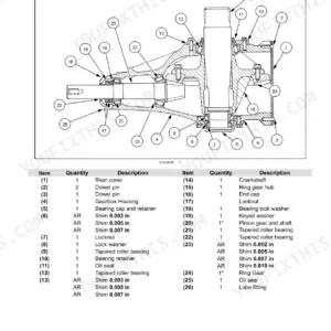
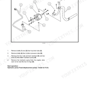
| Hydraulic System | 141-230 | Combine Adapter Schematics (Forward and Reverse, Inner and Outer Pump, Over Relief), Delta and HydraForce Selector Valves, Hydraulic Testing (RV1/RV2/RV3 Relief Settings, Sequence Valve, Flow and Pump Output), Hydraulic Oil Specifications and Change Procedure, Reel Lift Cylinders, Static and Dynamic Diagnostic Tests, Hydraulic Motor Repair (Gerotor and Shaft Ends, Timing), Retracting Tine Drum and Feed Draper Motors, Gearbox and Pump Repair, Valve Block |
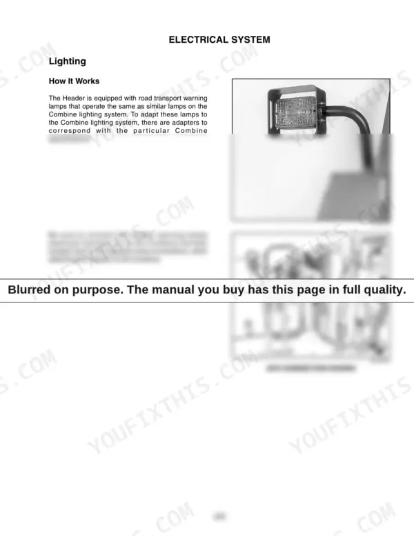
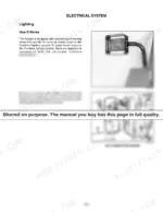
| Electrical System | 231-258 | Lighting, Electrical Schematics (Pre and Post P.I.N. Break), Transport Option Electrical System (Normal Driving and Turning Modes), Selector Valve Setup for 2300 Series and AFX Combines, Delta and Hydraforce Coil Resistance, Float Optimizer, Adjusting the Sensor Range, Potentiometer Troubleshooting |
| Linkage and Suspension | 259-286 | Header and Combine Adapter (How It Works), Suspension Assembly (How It Works), Adapter Suspension Repair, Disconnecting Adapter From Header |
| Structure | 287-288 | Impact Repairs (How It Works, Cutter Bar Stringing, Impact Repair Parts) |
| Header Wing Removal | 289-330 | Reel Removal (Right Reel Removal, Left Reel Removal) |
| Float Optimizer | 331-344 | Adjustment and Operation, Combine Calibration (and 2300 Series Combine Configuration, Operation) |
Quick Reference Specifications
| Specification | Value | Page |
|---|---|---|
| Relief pressure | 137.896 bar [13789.5 kPa] (2000 psi) | p. 31 |
| Float setting for Dry Ground | 45.36 to 68.04 kg (100 to 150 pounds) | p. 38 |
| Float setting for Wet Ground | 22.68 to 45.36 kg (50 to 100 pounds) | p. 38 |
| Internal bearing lock collar to end measurement | 1110 mm (43-45/64 inches) | p. 54 |
| Right end nearing lock collar to end measurement | 65 mm (2-1/2 inches) | p. 54 |
| Torque for 5/8 x 3 inch bolt (3) to secure arm on spline | 217 Nm (160 foot pounds) | p. 79 |
| Torque for 5/8 x 3 inch hex bolt on knife head pin | 217 Nm (160 foot pounds) | p. 79 |
| Reel drive chain tension | 50 N (11 pounds) deflects the chain 3 mm (1/8 inch) at mid-span | p. 136 |
| Large sprocket nut torque | 50 Nm (40 foot pounds) | p. 136 |
| Hydraulic oil filter change interval | after the first 50 hours of operation and 250 hours thereafter | p. 167 |
| Face plate bolts torque | 40 Nm (30 ft. lbs.) | p. 218 |
| Retaining nut torque | 40 Nm (30 ft. lbs.) | p. 218 |