Part of the Case Repair Manuals.
When a Case skid steer will not track straight, the loader arm refuses to lift or the cluster starts a 30 second shutdown countdown, this book walks the checks in order, from charge pressure to the code procedure. It is the factory service manual 47851948 for the Alpha Series Tier 4B Final SR210, SR240, SV280 skid steers and TR270, TR310 compact track loaders.
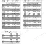
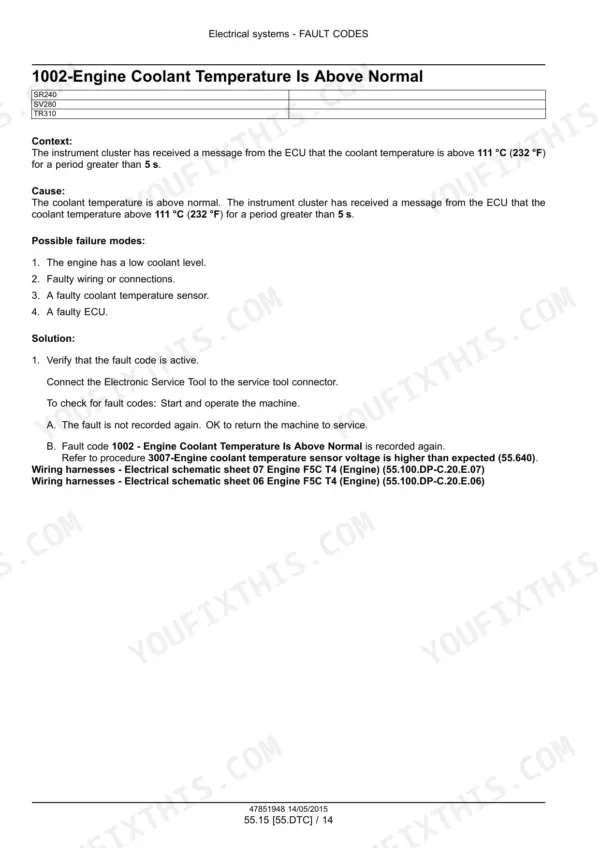
It covers engine removal and fluids, the hydrostatic drive with pump pressure tests and decontaminating, hydraulic systems with schematic frames, axles and chain drive, tracks, climate control, the complete electrical system with schematic sheets and harness views, and a fault code section from page 1176 to 2014 with cause, failure modes and solution steps for each code. Capacities, standard torque tables and fold out electrical and hydraulic schematics are included.
What's Inside This Manual
| System | Pages | Key Topics |
|---|---|---|
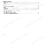
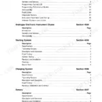
| Introduction | 9-32 | Safety Rules, Torque Tables, Hydraulic Contamination, Biodiesel Fuel, Capacities, Product Identification |
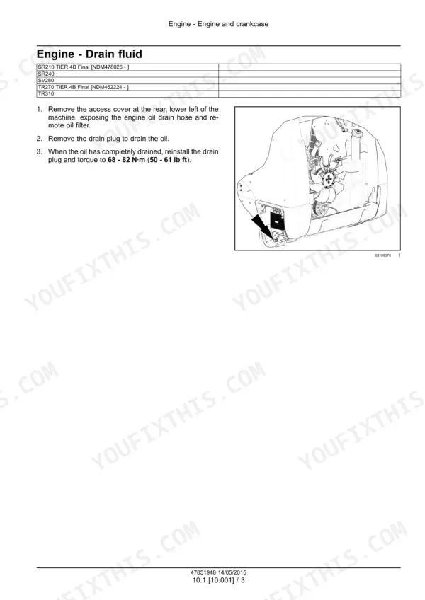
| Engine | 33-96 | Engine and Crankcase Removal and Filling, Fuel Tanks, EGR, Diesel Particulate Filter, Engine Cooling and Lubrication |
| Power Coupling | 97-104 | Pump Drive Assembly |
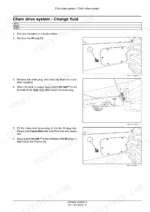
| Axle Systems | 105-152 | Front and Rear Axle, Chain Drive Check |
| Hydrostatic Drive | 153-326 | Mechanical Control Adjustment, Pump and Motor Components, Pressure Tests, Hydrostatic Transmission Decontaminating and Troubleshooting, Two Speed |
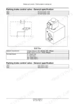
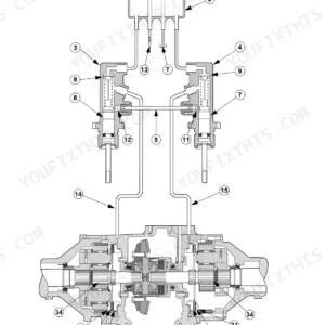
| Brakes and Controls | 327-340 | Parking Brake |
| Hydraulic Systems | 341-538 | Hydraulic Schematic Frames, Reservoir, Cooler and Filters, Gear Pump, Main Control Valve, Auxiliary Valves, Loader Arm Troubleshooting |
| Frames, Wheels and Tracks | 539-596 | Ballasting, Wheels, Rubber Track Tension and Track Frames |
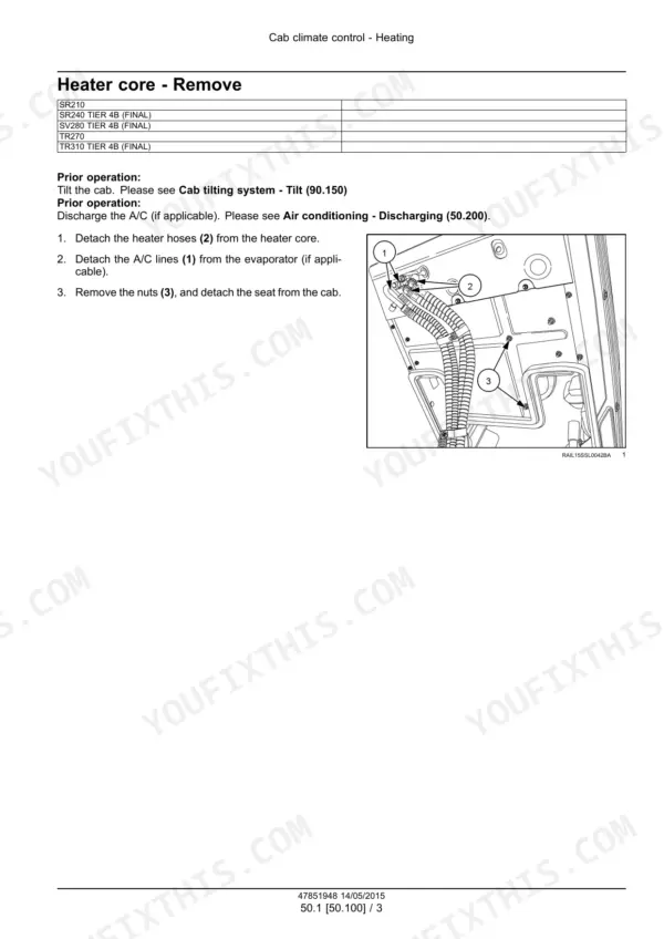
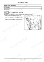
| Cab Climate Control | 597-644 | Air Conditioning Charging and Components |
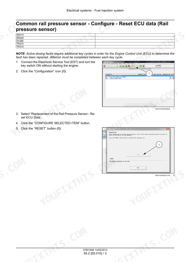
| Electrical System and Engine Controls | 645-697 | Fuel Injection, Fuel Tank, Engine Cooling, Hydrostatic Drive and Hydraulic System Controls, HVAC Controls |
| Harnesses and Connectors | 698-1113 | Electrical Schematic Sheets, Harness and Connector Views |
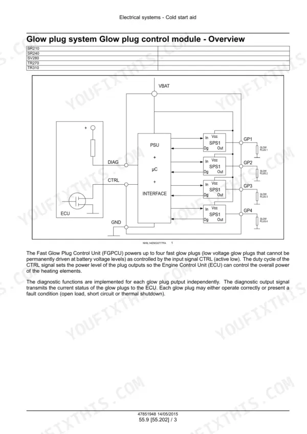
| Electrical Components | 1114-1175 | Cold Start Aid, Battery, Warning Indicators, Cab Controls and EZ-EH Setup, Wiper and Washer, Electronic Modules and CAN Bus |
| Fault Codes | 1176-2014 | Diagnostic Trouble Codes with Context, Cause, Failure Modes and Step by Step Solutions |
| Loader, Cab and Bodywork | 2015-2099 | Front Loader and Bucket, Platform, Cab, Bodywork and Decals |
| Special Tools and Fold Out Schematics | 2100-2120 | Special Tool Index, EH and Mechanical Machine Electrical Schematics, Hydraulic Schematic |
Quick Reference Specifications
| Specification | Value | Page |
|---|---|---|
| SR210, TR270, TR310 | ||
| Fuel tank capacity (SR210, TR270, TR310) | 75.5 L (20.0 US gal) | p. 27 |
| Cooling system capacity (SR210, TR270, TR310) | 17.0 L (4.5 US gal) | p. 27 |
| Hydraulic system capacity (SR210, TR270, TR310) | 38.1 L (10.0 US gal) | p. 27 |
| SR240, SV280 | ||
| Fuel tank capacity (SR240, SV280) | 95.5 L (25.5 US gal) | p. 27 |
| Cooling system capacity (SR240, SV280) | 19.0 L (5.0 US gal) | p. 27 |
| Hydraulic system capacity (SR240, SV280) | 45.4 L (12.0 US gal) | p. 27 |
| Chain compartment capacity, each side (SR240, SV280) | 22.2 L (23.5 US qt) | p. 27 |
| SR210, SR240, SV280, TR270, TR310 | ||
| Fuel | #1 or #2 Diesel ultra low sulfur | p. 27 |
| Hydraulic reservoir capacity | 15.0 L (3.96 US gal) | p. 27 |
| Hydraulic oil | TUTELA AUTO SUPREME ENGINE OIL SAE 10W-30 | p. 27 |
| Engine crankcase oil capacity with filter change | 8.5 L (9.0 US qt) | p. 27 |
| Engine oil | CASE AKCELA UNITEK NO. 1 SBL CJ-4 | p. 27 |
| SR210 | ||
| Chain compartment capacity, each side (SR210) | 26.0 L (27.5 US qt) | p. 27 |
| TR270, TR310 (tracked models) | ||
| Final track drive capacity, each side (TR270, TR310) | 1.0 L (1.06 US qt) +/- 0.1 L (0.1 US qt) | p. 28 |
| Final track drive lubricant (TR270, TR310) | TUTELA HYPOIDE EP GEAR LUBE SAE 80W-90 | p. 28 |
| SR210, SR240, SV280, TR270, TR310 (mechanical hydraulic controls) | ||
| Hydrostatic pump displacement (mechanical hydraulic controls) | 46 cm³ (2.8 in³) | p. 165 |
| Charge pump flow at 1800 RPM (mechanical hydraulic controls) | 30 l (8 US gal) | p. 165 |
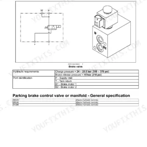
| Charge pressure relief valve setting (mechanical hydraulic controls) | 24 - 25 bar (350 - 370 psi) at 1800 RPM | p. 165 |
| Drive circuit pressure limiter valves (mechanical hydraulic controls) | 360 - 378 bar (5220 - 5481 psi) | p. 165 |
| Charge pressure relief valve torque (mechanical hydraulic controls) | 109 N·m (80 lb ft) | p. 166 |