Part of the Case Repair Manuals.
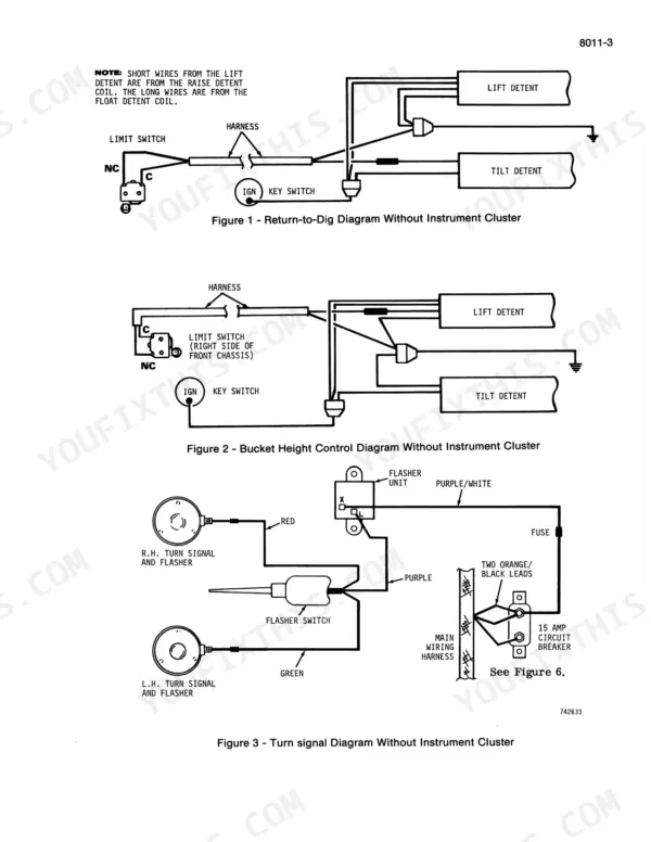
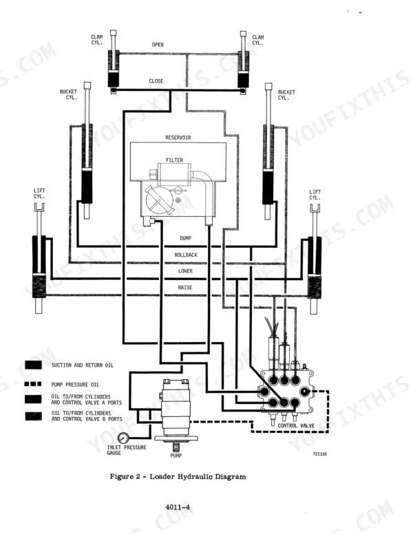
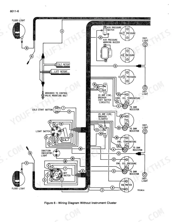
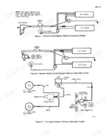
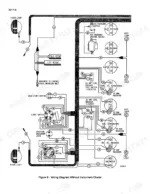
The Case W14 service manual PDF breaks the W14 loader down system by system across 813 pages under Case OEM ID 9-72536, from engine tune-up and the Robert Bosch injection pump through the Allison powershift transmission and air brakes. Hydraulic diagrams trace the loader circuit through the L51290 and L52776 loader control valves, with separate backhoe diagrams and pressure checks for the Model 26C backhoe. Electrical work starts from a wiring diagram for machines without instrument clusters, then moves through batteries, the starter solenoid and both alternators. Set injectors to open at 3200 PSI, then confirm 400 PSI cranking compression (480 PSI running) with the gauge adapter torqued to 35 to 45 ft. lbs. If steering troubleshooting brought you here, the steering hydraulic diagram shows how the steering control valve, flow control valve and steering cylinders connect. The bookmarked, text-searchable file goes wherever your W14 does.
What's Inside This Manual
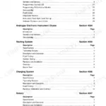
| System | Pages | Key Topics |
|---|---|---|
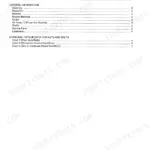
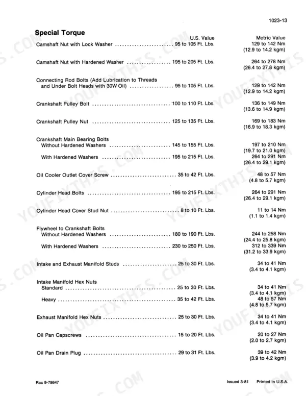
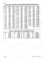
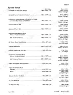
| General | 7-32 | Detailed Engine Specifications, Maintenance and Lubrication, Torque Chart |
| Engine | 33-222 | Engine Diagnosis, Engine Tune-Up, Cylinder Head, Valve Train and Camshaft, Cylinder Block, Sleeves, Pistons and Rods, Crankshaft |
| Fuel System | 223-276 | Fuel System and Filters, Robert Bosch Fuel Injection Pump, Roosa Master Fuel Injectors, Electric Fuel Pump, Fuel Lines and Fuel Tank |
| Hydraulics | 277-389 | Hydraulic Diagram, Trouble Shooting, Testing and Adjustments, Backhoe Hydraulic Diagrams, Pressure Checks, Hydraulic Pump, L51290 and L52776 Loader Control Valves |
| Steering | 390-429 | Hydraulic Diagram, Trouble Shooting and Testing, Steering Control Valve and Flow Control Valve, Steering Cylinders, Center Pivot |
| Power Train | 430-603 | Allison Transmissions - Powershift Model, Transmission Removal and Installation, Differentials and Planetaries, Rear Axle Trunnion Center Bearing Support |
| Brakes | 604-693 | Air System Operation and Diagram, Pressurizing/Depressurizing the Air System, Brake Shoes and Wheel Cylinders, L52092 Air Compressor, Governor and Reservoir, L17683 Air Compressor |
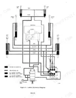
| Electrical | 694-775 | Wiring Diagram - Machines Without Instrument Clusters, Trouble Shooting and Adjustments, Batteries, Starter, Starter Solenoid and Magnetic Switches, Amp Alternator |
| Mounted Equipment | 776-813 | Loader, Model 26C Backhoe, Roll-Over Protection Structure |
Quick Reference Specifications
| Specification | Value | Page |
|---|---|---|
| Fuel Injectors Opening Pressure | 3200 PSI | p. 7 |
| Cranking Method Compression Pressure | 400 PSI | p. 76 |
| Compression Gauge Adapter Torque | 35 to 45 ft. lbs. | p. 76 |
| Compression Gauge Adapter Torque (Clamp Type) | 20 ft. lbs. | p. 75 |
| Water pressure limit for cleaning primary element | 40 psi | p. 205 |
| Compressed air pressure limit for cleaning primary element | 30 psi | p. 205 |
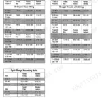
| Hydraulic Fittings (Steel) 4 Dash Size Torque | 6-12 Ft-lbs (8-16 Nm) | p. 279 |
| Hydraulic Fittings (Steel) 5 Dash Size Torque | 8-16 Ft-lbs (11-21 Nm) | p. 279 |
| Piston Retaining Bolts Torque (Clam Cylinder - 3/4" - 16 thread) | 200-220 ft-lbs (271-298 N m) | p. 368 |
| Piston Retaining Bolts Torque (Bucket Cylinder - 1" - 14 thread) | 475-525 ft-lbs (644-712 N m) | p. 368 |
| Bearing extension | 1/4 inch | p. 425 |
| Engine Oil Pressure (warm, rated speed) | 45 to 60 Pounds | p. 7 |