

Part of the Hyundai Repair Manuals.
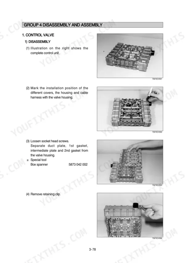
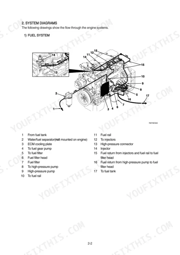
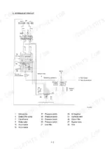
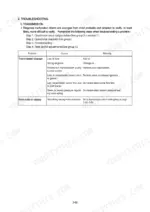
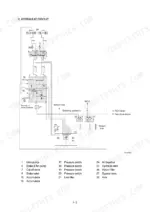
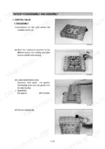
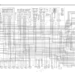
All 502 pages of this Hyundai HL740-7A, HL740XTD-7A, HL740TM-7A service manual PDF focus on one job: getting your wheel loader back to factory spec, whether you run the standard, XTD, or TM version. Inside: factory hydraulic schematics, complete electrical circuit diagrams with connector pinouts, and a dedicated error-code section for tracing monitor faults. You also get step-by-step disassembly and assembly for the power train, brakes, steering, and work equipment, backed by operational checks, troubleshooting, and test procedures for every system. Torque the tire mounting nuts to 70±2.0 kgf·m (506±15 lbf·ft) and set the transmission system pressure valve at 16+2 bar. Your loader is down and every idle hour costs money. Get the factory numbers, not forum guesses. Bookmarked with a full text layer: search any spec, jump straight to the section, and get back to work.
What's Inside This Hyundai HL740-7A, HL740XTD-7A, HL740TM-7A Manual
| System | Pages | Key Topics |
|---|---|---|
| General | 1-38 | Safety Hints, Specifications, Operational Checkout Record Sheet |
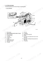
| Engine | 39-47 | Structure and Function, Fuel Warmer System, Engine Speed and Stall RPM |
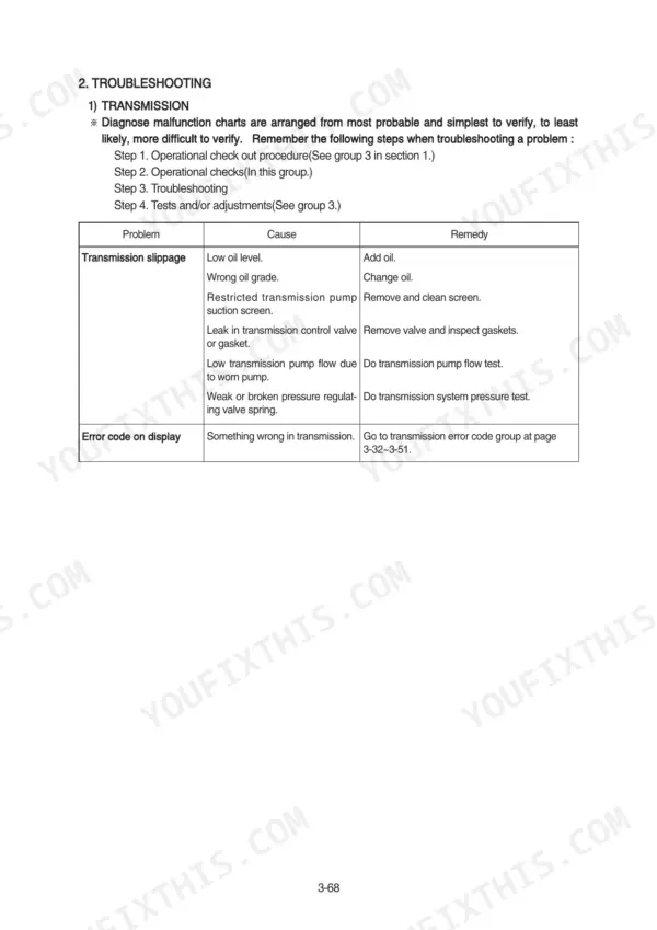
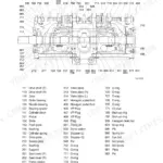
| Power Train System | 48-229 | Power Train Component Overview and Layout, Center Drive Shaft, Transmission, Torque Converter, Axles, Operational Checks and Troubleshooting, Disassembly and Assembly, Maintenance Standard |
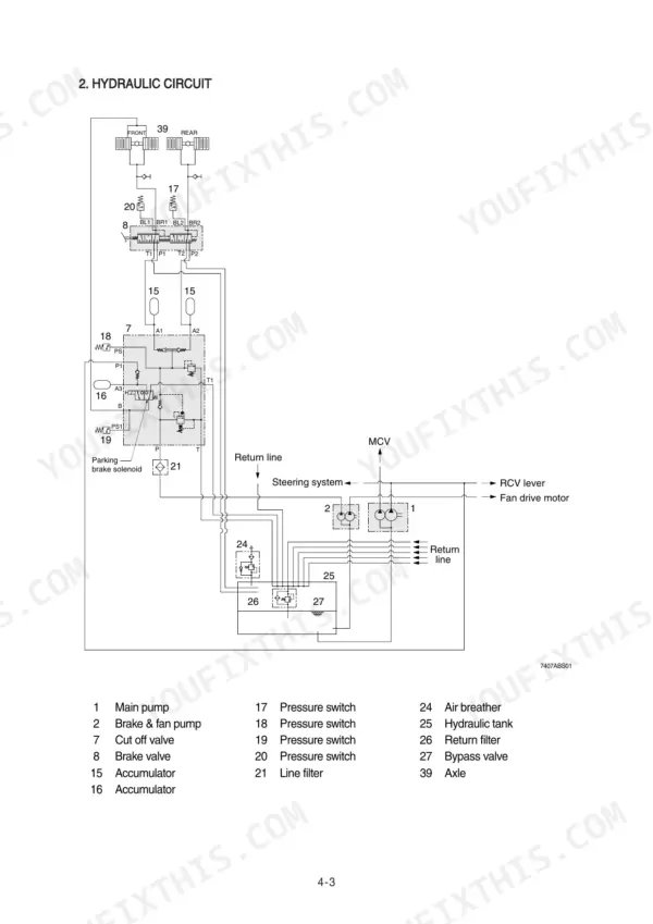
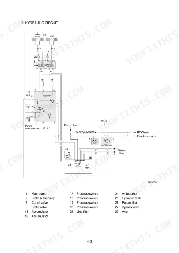
| Brake System | 230-268 | Full Power Hydraulic Brake Outline and Advantages, Air/Hydraulic Brake Actuation, Accumulator, Air Breather, Operational Checks and Troubleshooting, Disassembly and Assembly, Maintenance Standard |
| Steering System | 269-338 | Steering Structure and Operation, 1st and 2nd Pump, Air Breather, Priority and Steering Valves, Operational Checks and Troubleshooting, Disassembly and Assembly, Maintenance Standard |
| Work Equipment | 339-425 | Hydraulic System Outline, Accumulator (Incl. Option), Air Breather, Loader Linkage and Cylinders, Operational Checks and Troubleshooting, Disassembly and Assembly, Maintenance Standard |
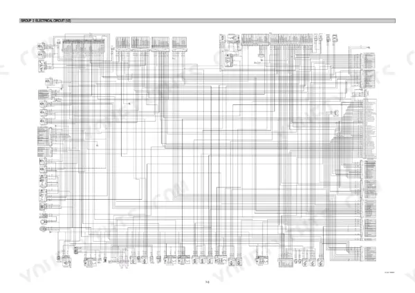
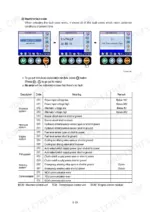
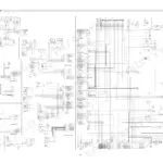
| Electrical System | 426-502 | Component Location, Electrical Circuit, Monitoring System, Electrical Component Specification, Connectors, Troubleshooting |
Quick Reference Specifications
| Specification | Value | Page |
|---|---|---|
| Tire mounting nut(20.5-25 16PR, L3) | 70±2.0 kgf·m (506±15 lbf·ft) | p. 32 |
| Maxi fuse rating | 20A | p. 46 |
| Pressure reducing valve | 9 bar | p. 62 |
| System pressure valve | 16+2 bar | p. 62 |
| Clamping torque for M18 x 1.5, 10K screws | 46.9~47.4 kgf·m (339~343 lbf·ft) | p. 203 |
| Battery relay rated load | 24V 100A(Continuity) 1000A(30seconds) | p. 467 |
| Engine Oil Quantity | 16 L | p. 29 |
| Main Relief Valve Set Pressure | 220 kgf/cm2 | p. 30 |
| Engine High Idling Speed | 2230 +/- 50 rpm | p. 29 |
| Engine Low Idling Speed | 950 +/- 25 rpm | p. 29 |
| Brake Accumulator Charging Pressure | 50 kgf/cm2 | p. 247 |
| Main Control Valve Relief Pressure | 220 kgf/cm2 | p. 393 |
Hyundai HL740-7A, HL740XTD-7A, HL740TM-7A Common Problems This Manual Covers
Hyundai HL740-7A transmission won't shift, dash gear indicator doesn't follow selector input
Check the steering column gear selector connector and wiring before condemning the TCU. Read stored fault codes with the error code reference, then follow the troubleshooting procedures. Verify transmission system pressure reaches 16+2 bar; low clutch pressure mimics selector faults. Replace the selector switch only after confirming signal loss at the TCU connector.
Manual Section: Power Train SystemLoader slowly loses hydraulic power and transmission oil level rises after a few hours of work
Drain the transmission back to the correct level and check the oil for thin, hydraulic-contaminated fluid. Replace the hydraulic pump shaft seal; a failed seal lets hydraulic oil migrate into the transmission housing. After repair, test main relief pressure against the 220 kgf/cm2 setting on page 393, then recheck both oil levels after a full shift.
Manual Section: Work Equipment p. 393Engine won't crank or cranks intermittently, buzzer and alarms act up at random
Check the 20A maxi fuses listed on page 46 first, then clean and tighten battery terminals and cable ends. Test the battery relay against its 24V, 100A continuous rating on page 467; a corroded relay drops voltage under crank load. Trace the starting switch circuit with the wiring diagram before replacing the MCU.
Manual Section: Electrical System p. 467Brakes feel weak and pedal takes several pumps after machine sits overnight
Test accumulator precharge against the 50 kgf/cm2 charging pressure spec on page 247 with the engine off and the pedal pumped down. Recharge or replace a flat accumulator with dry nitrogen only. Inspect the charging valve and brake lines for external leaks, then confirm the warning lamp clears after several pedal applications with the engine running.
Manual Section: Brake System p. 247Bucket lifts slowly and pump whines under load once hydraulic oil warms up
Check hydraulic oil level and inspect the suction line for air leaks; a whining pump usually means cavitation. Test main relief pressure against the 220 kgf/cm2 setting on page 393 at full engine speed. Verify the pilot accumulator holds its 16 kg/cm2 charge per page 375; weak pilot pressure slows spool response. Replace the pump only after pressures test correct.
Manual Section: Work Equipment p. 393Frequently Asked Questions
What do the fault codes mean on a Hyundai HL740-7A wheel loader?
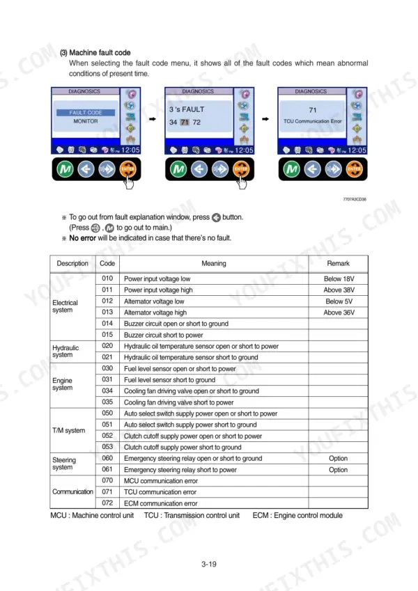
Fault codes on the HL740-7A indicate specific system abnormalities. For example, code 010 indicates 'Power input voltage low' (below 18V), while code 011 indicates 'Power input voltage high' (above 38V). Other codes cover hydraulic, engine, and transmission system faults, such as code 031 for 'Fuel level sensor short to ground'. p. 67
What is the tightening torque for the transmission mounting bolts (bracket, rear)?
The tightening torque for the transmission mounting bolts (bracket, rear) is 18.4 ± 2.0 kgf·m (133 ± 14.5 lbf·ft). p. 32
What is the engine oil capacity for the Cummins QSB6.7 engine?
The engine oil capacity for the Cummins QSB6.7 engine is 16 liters (4.2 U.S. gal). p. 29
What is the procedure for bleeding the hydraulic brake system?
Bleeding the brake system requires two people: one to operate the brake valve and another to open and close the bleed screws. You must install a frame locking bar, engage the parking brake, and route a clear plastic tube from the bleed screw (B) to the hydraulic reservoir filler tube or container (A). Push and hold the brake pedal down until the bleeding procedure is complete. p. 262
What is the maximum allowable leakage for the steering unit during a leakage test?
The maximum allowable leakage for the steering unit is 10 liters per minute (10 ℓ/min). p. 293
Will this Hyundai HL740-7A Service Manual download right away?
You download the Service Manual yourself: 502 pages, searchable PDF, available immediately. Keep a copy on every device you use.
Am I able to print pages from this Hyundai HL740-7A manual?
Yes. Print the pages you need for the job in your own shop, and bin them when they get greasy.








Reviews
There are no reviews yet.