
Part of the Hyundai Repair Manuals.
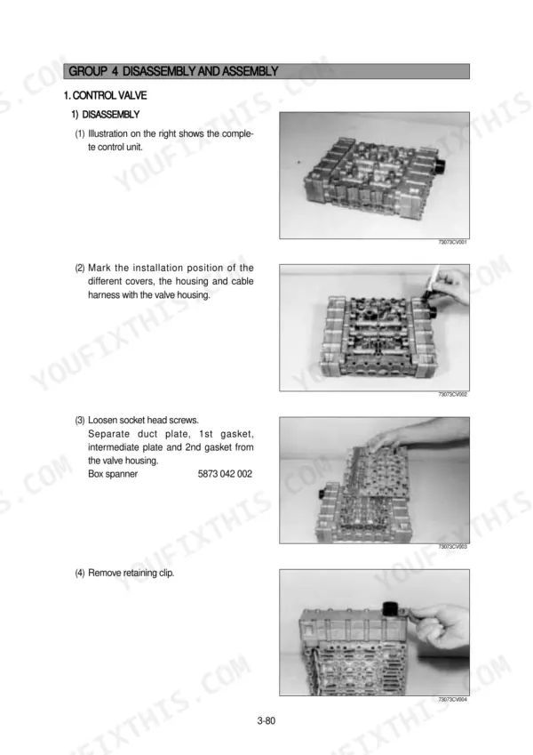
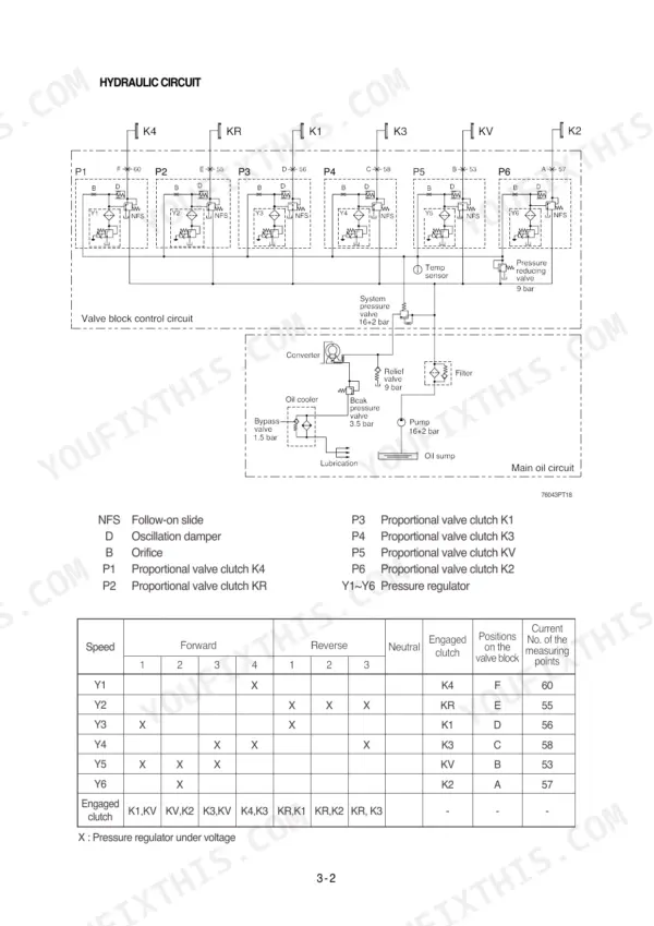
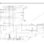
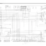
All 920 pages of this Hyundai HL760-7 Service Manual PDF cover one machine: your HL760-7 Wheel Loader, from power train to work equipment. Inside you get factory wiring diagrams with connector pinouts, hydraulic schematics tracing the main control valve and pilot circuits, and step-by-step disassembly and assembly procedures for the transmission, brakes, and steering. Troubleshooting charts walk you from symptom to fix on every major system, backed by tests and adjustments for pump flow and relief pressure. Need real numbers? Torque the tire mounting nuts to 61 kgf·m and set the steering pump relief at 210 kgf/cm². When a loader sits dead in the yard, forum threads won't cut it; factory data will. Bookmarked chapters and a live text layer take you straight to any spec. Download it, open it on your phone, and get that loader digging again.
What's Inside This Hyundai HL760-7 Manual
| System | Pages | Key Topics |
|---|---|---|
| General | 1-9 | Safety Hints, Specifications, Operational Checkout Record Sheet |
| Electrical System | 10-35 | Component Location, Electrical Circuit, Monitoring System, Electrical Component Specification, Connectors, Troubleshooting |
| Engine | 36-40 | Structure and Function |
| Power Train System | 41-215 | Structure and Function, Operational Checks and Troubleshooting, Tests and Adjustments, Disassembly and Assembly |
| Brake System | 216-255 | Structure and Function, Operational Checks and Troubleshooting, Tests and Adjustments, Disassembly and Assembly |
| Steering System | 256-316 | Structure and Function, Operational Checks and Troubleshooting, Tests and Adjustments, Disassembly and Assembly |
| Hydraulic System Outline and Circuit Diagrams | 317-326 | Hydraulic System Overview, Main Control Valve, Boom Section Operation, Bucket Section Operation, Main Relief Valve |
| Main Pump Structure and Operation | 327-328 | Main Pump Structure, Gear Pump Operation, Internal Oil Leakage, Forces Acting on the Gear |
| Remote Control Valve | 329-331 | Remote Control Valve Structure, Hydraulic Functional Principle, End Position Lock, Electromagnetic Lock |
| Main Control Valve Structure and Operation | 332-344 | Main Control Valve Structure, Port Relief Valve, Overload Relief Function, Make-Up Valve |
| Pilot Oil Supply Unit | 345-347 | Pilot Oil Supply Unit Structure, Accumulator Operation, Boom and Bucket Cylinder Structure |
| Hydraulic Oil Tank and Filters | 348-351 | Hydraulic Oil Tank Structure, Return Oil Filter Bypass Valve, Air Breather, Accumulator |
| Operational Checks and Troubleshooting | 352-362 | Hydraulic System Warm-Up, Hydraulic Pump Performance Check, Control Valve Lift Check, Cylinder Drift Test, Leakage Test |
| Tests, Adjustments and Maintenance | 363-470 | Hydraulic Oil Clean Up, Boom Height Kickout Adjustment, Test Tools, Main Hydraulic Pump Flow Test, Loader System Relief Pressure Test |
| Second Volume, General and Specifications | 471-495 | Safety Hints, Machine Specifications, Operational Checkout Record Sheet |
| Second Volume, Power Train System | 496-670 | Structure and Function, Transmission, Torque Converter, Axles, Operational Checks and Troubleshooting, Disassembly and Assembly |
| Second Volume, Brake System | 671-710 | Structure and Function, Service and Parking Brake, Operational Checks, Tests and Adjustments |
| Second Volume, Steering System | 711-771 | Structure and Function, Steering Unit, Operational Checks, Tests and Adjustments, Disassembly and Assembly |
| Second Volume, Work Equipment | 772-853 | Hydraulic Circuit, Main Pump, Control Valve, Cylinders, Tests and Adjustments |
| Second Volume, Electrical System | 854-920 | Component Location, Electrical Circuits, Monitoring System, Connectors |
Quick Reference Specifications
| Specification | Value | Page |
|---|---|---|
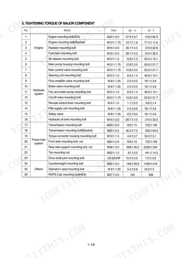
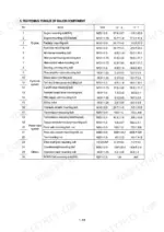
| Tire mounting nut | 61 ± 2.0 kgf·m | p. 29 |
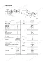
| Transmission pump (Main pump) capacity | 68+63 cc/rev | p. 27 |
| Main pump (Steering) maximum operating pressure | 210 kgf/cm² | p. 27 |
| Brake + Fan pump maximum operating pressure | 180 kgf/cm² | p. 27 |
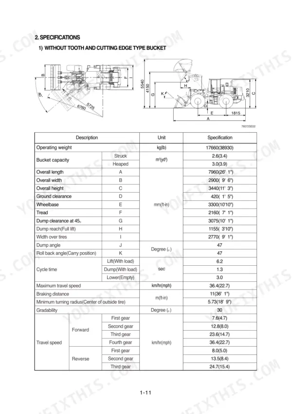
| Engine Oil Quantity | 16 L | p. 26 |
| Rated Horse Power | 218 ps | p. 26 |
| Main Relief Valve Pressure | 210 kgf/cm2 | p. 27 |
| Brake Pump Max Operating Pressure | 180 kgf/cm2 | p. 27 |
Hyundai HL760-7 Common Problems This Manual Covers
Hyundai HL760-7 transmission won't shift, drive pressure low, machine will not move in low gear
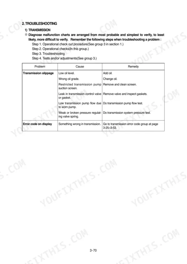
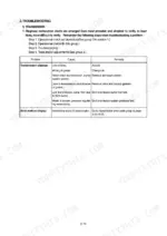
Check clutch pressure at the test ports using the transmission troubleshooting steps. If pressure climbs slowly, suspect the transmission pump; rated displacement is 68+63 cc/rev, and a worn pump shows up as lazy pressure rise. Replace the control valve gasket and clutch piston seal rings if pressure bleeds down in gear.
Manual Section: Transmission TroubleshootingBoom and bucket weak or slow under load, hydraulic functions fade once oil warms up
Verify hydraulic oil level and warm the system, then run the pump performance check starting on page 352. Test main relief pressure; it should hold 210 kgf/cm2. If pressure checks good but functions stay slow, pull the suction strainer and return filter and look for a plugged element or collapsed suction line.
Manual Section: Operational Checks and Troubleshooting p. 352Steering heavy and slow at low idle, needs constant correction to hold straight travel
Check steering relief and pump output before condemning the steering valve. The steering pump should develop 210 kgf/cm2 maximum; a low reading points to a worn pump or dirt-plugged relief valve. Clean the relief valve and orifices, then work through the steering system procedures beginning on page 256 to isolate a stuck spool.
Manual Section: Steering System p. 257Hydraulic pump whines or growls on startup, oil in tank looks foamy
Inspect the suction line for air leaks and tighten every clamp between tank and pump; foam almost always means air ingress, not a bad pump. Top up the oil, then run a flow test against the 68+63 cc/rev pump rating using the procedures on page 363. Replace the air breather and suction strainer while you are in there.
Manual Section: Tests, Adjustments, and Maintenance p. 363Service brakes feel spongy, pedal travel long, machine won't hold on a grade
Bleed the service brakes and check accumulator charge first. Verify the brake pump develops its 180 kgf/cm2 maximum operating pressure; low output means a worn pump, not just air in the lines. Follow the brake system section starting on page 216 to test the brake valve and measure disc wear.
Manual Section: Brake System p. 217Frequently Asked Questions
What is the torque specification for the wheel lug nuts on the Hyundai HL760-7?
The tightening torque for the tire mounting nuts (wheel lug nuts) on the Hyundai HL760-7 is 61 ± 2.0 kgf·m (441 ± 14.5 lbf·ft). p. 29
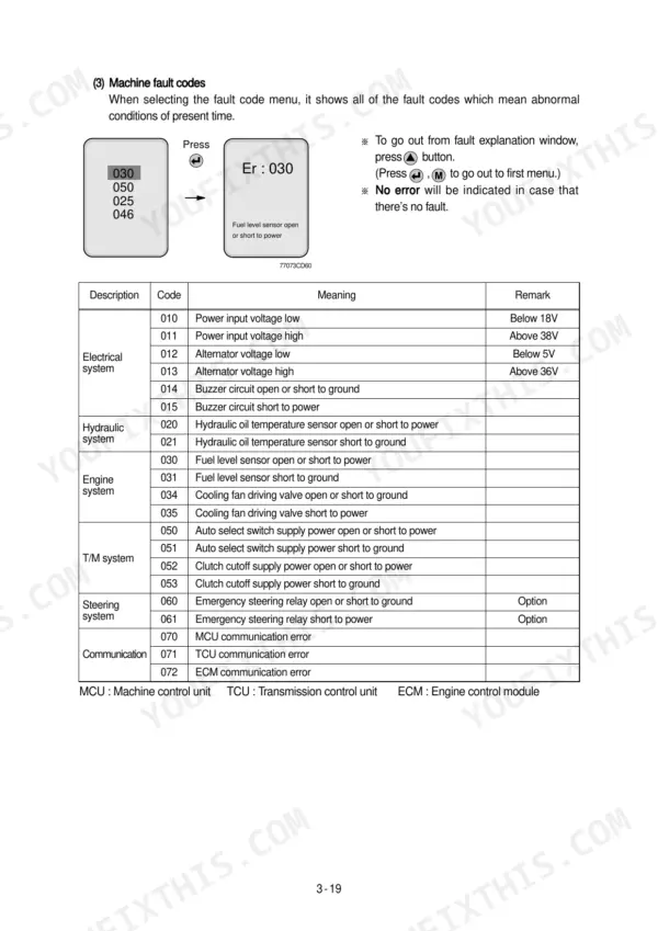
How do I reset a transmission fault code on the HL760-7?
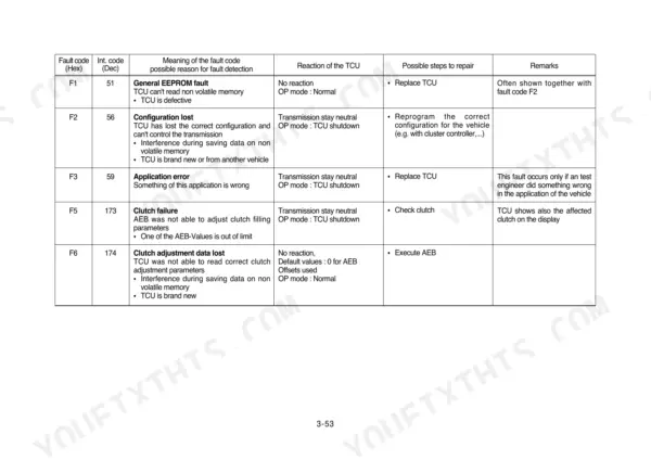
To reset a transmission fault code, you must first address the underlying issue. Once the fault is corrected, the fault code is typically reset after powering up the TCU (Transmission Control Unit). p. 68
What is the engine oil capacity for the Cummins QSB5.9 engine in the HL760-7?
The engine oil capacity for the Cummins QSB5.9 engine is 16 liters (4.2 U.S. gallons). p. 26
What is the procedure for bleeding the hydraulic brake system?
Bleeding the brake system requires two people: one to operate the brake valve and another to open and close the bleed screws. Push and hold the brake pedal down until the bleeding procedure is complete; if bubbles continue for more than 2 minutes, stop and check for problems. p. 249
What is the standard torque for the engine mounting bolts on the HL760-7?
The engine mounting bolts (2EA) require a tightening torque of 57.9 ± 8.7 kgf·m (419 ± 62.9 lbf·ft). p. 29
How quickly can I access this Hyundai HL760-7 manual after buying?
This is a 920-page searchable PDF ready for immediate download. Works on any device, so pull it up on your phone while you're under the hood. No shipping, no waiting.
Can I print this Hyundai HL760-7 manual?
Yes. It prints from any PDF reader, so run off the pages you need for your own repair work.






Reviews
There are no reviews yet.