
Part of the Hyundai Repair Manuals.
Looking for a Hyundai R180LC-7A, R180NLC-7A service manual PDF you can actually trust? This 490-page factory service manual covers both hydraulic excavator variants, standard and narrow track, from safety hints to final component mounting torques. Inside: full hydraulic schematics tracing the main and pilot circuits through single and combined operation, complete wiring diagrams with connector pinouts, and a thick troubleshooting section for hydraulic, electrical, and mechatronics faults. Step-by-step teardown procedures walk you through the pump, main control valve, swing and travel devices, turning joint, and cylinders. Set pilot relief at 35 kgf/cm2, hold boom, arm, and bucket relief at 330 kgf/cm2, and replace the swing bearing once thrust clearance passes 0.8 mm. Your machine is down; get the factory numbers, not forum guesses. Bookmarked with a live text layer, so you can jump to any section or search any spec right from the tablet in your cab.
What's Inside This Hyundai R180LC-7A, R180NLC-7A Manual
| System | Pages | Key Topics |
|---|---|---|
| General | 11-38 | Safety Hints, Specifications |
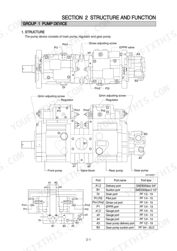
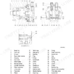
| Structure and Function | 39-115 | Pump Device, Main Control Valve, Swing Device, Travel Device, Rcv Lever, Rcv Pedal |
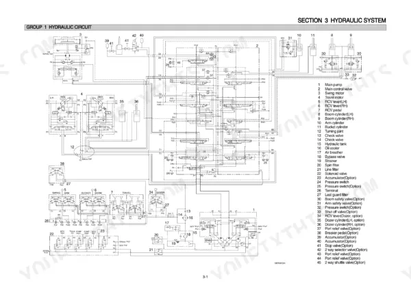
| Hydraulic System | 116-147 | Hydraulic Circuit, Main Circuit, Pilot Circuit, Single Operation, Combined Operation |
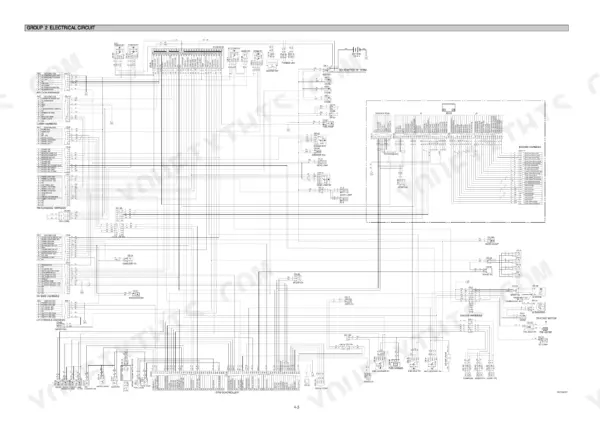
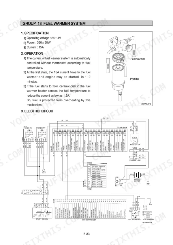
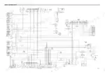
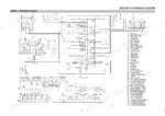
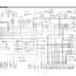
| Electrical System | 148-199 | Component Location, Electrical Circuit, Electrical Component Specification, Connectors |
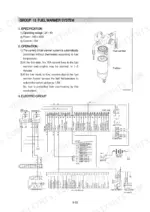
| Mechatronics System | 200-233 | Outline, Mode Selection System, Automatic Deceleration System, Power Boost System, Travel Speed Control System, Automatic Warming Up Function, Engine Overheat Prevention Function |
| Maintenance Standard | 284-320 | Operational Performance Test, Major Components, Track and Work Equipment |
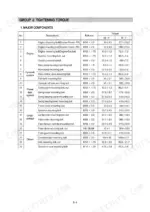
| Disassembly and Assembly | 321-476 | Precaution, Tightening Torque, Pump Device, Main Control Valve, Swing Device, Travel Device, Rcv Lever, Turning Joint |
| Component Mounting Torque | 477-490 | Introduction Guide, Engine System, Electric System, Undercarriage, Structure, Work Equipment |
Quick Reference Specifications
| Specification | Value | Page |
|---|---|---|
| All Models | ||
| Bypass relief valve setting pressure | 1.5kgf/cm2 (21psi) | p. 119 |
| Bypass check valve (1) setting pressure | 3.0kgf/cm2 (43psi) | p. 119 |
| Maximum allowable value for thrust bearing clearance | 0.8mm | p. 308 |
| Standard dimension for axial clearance between coupling gear and cover | 0.3 to 0.6mm | p. 308 |
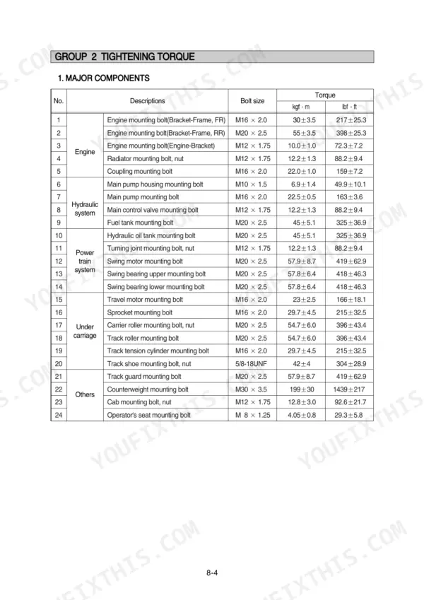
| Carrier roller mounting bolt, nut | 54.7 ± 6.0 kgf·m | p. 325 |
| Track roller mounting bolt | 54.7 ± 6.0 kgf·m | p. 325 |
| Swing bearing upper mounting bolt | 57.8 ± 6.4 kgf·m | p. 325 |
| Swing bearing lower mounting bolt | 57.8 ± 6.4 kgf·m | p. 325 |
| R180LC-7A | ||
| Standard relief pressure for Boom, Arm, Bucket | 330(360) kgf/cm2 | p. 304 |
| Maximum allowable relief pressure for Boom, Arm, Bucket | 380 kgf/cm2 | p. 304 |
| Operating weight, R180LC-7A | 18200 kg | p. 21 |
| R180NLC-7A | ||
| Operating weight, R180NLC-7A | 18110 kg | p. 22 |
Hyundai R180LC-7A, R180NLC-7A Common Problems This Manual Covers
Hyundai R180LC-7A all hydraulic functions weak, boom and bucket lose power under load
Test main pump pressure with hydraulic oil at operating temperature; the pump should build 330 kgf/cm2 as listed on page 35. If it falls short, work through the weak-power steps starting, then remove and inspect the main relief valve, torquing it to 8~9 kgf·m (57.8~65.1 lbf·ft) on reinstall per page 362.
Manual Section: Hydraulic and Mechanical System Troubleshooting p. 6Boom, arm, or bucket cylinder drifts down slowly with the control lever in neutral
Test for internal leakage by swapping the suspect overload relief valve with a known-good valve from another circuit; the cylinder drift procedure covers this isolation check. Replace the valve if the drift follows it, then torque each overload relief valve to 8~9 kgf·m (57.8~65.1 lbf·ft) with a 32 mm spanner per page 362.
Manual Section: Hydraulic and Mechanical System Troubleshooting p. 6Swing motion sluggish or upper structure will not hold position on a slope
Check swing circuit relief pressure with a gauge; it should hold 240 kgf/cm2 per page 36. Low readings point to the swing motor relief valve, so follow the swing troubleshooting steps. If the machine creeps on a slope, verify the friction plate braking torque still measures 40.6 kgf·m or more against page 310.
Manual Section: Hydraulic and Mechanical System Troubleshooting p. 8Hydraulic oil cloudy or dark after tank filter failure, all functions erratic and weak
Drain the hydraulic tank completely (160 L capacity, page 328) and inspect the tank filter for a collapsed element and loose seal fragments. Flush the system following the contamination and cavitation procedures before refilling. After restart, verify drain oil pressure stays under the 1.5 kgf/cm2 (21 psi) limit shown on page 120.
Manual Section: Hydraulic and Mechanical System Troubleshooting p. 238Controls feel dead or laggy, attachments barely respond to pilot lever input
Measure pilot pressure at the RCV lever supply line; the pilot circuit relief valve is set at 35 kgf/cm2 per page 121. Low pilot pressure keeps the main control valve spools from stroking fully. Inspect the pilot filter and relief valve, and trace the circuit on the hydraulic schematic if pressure checks out.
Manual Section: Hydraulic System p. 121Frequently Asked Questions
How do I troubleshoot an error code on a Hyundai R180LC-7A?
When a trouble occurs, the CPU controller diagnoses the problem and stores error codes in its memory. You can view these codes on the cluster display. Refer to the 'Error Codes Table' on page 213 to identify the specific malfunction based on the code number and follow the corresponding troubleshooting procedure. p. 212
How do I clear or delete recorded error codes on the monitor?
To delete recorded error codes, navigate to the 'Diagnosis' menu on the cluster. Select 'Recorded Error' and then choose the option to delete all errors. The system will prompt you to confirm the deletion before clearing the memory. p. 212
What are the replacement specifications for the main relief valve?
The main relief valve should be replaced if it is damaged or if the contacting face of the poppet or valve seat is damaged. When reassembling, tighten the main relief valve to a torque of 8~9 kgf·m (57.8~65.1 lbf·ft). p. 306
What is the standard torque for tightening the main pump mounting bolts?
The standard torque for the main pump mounting bolts (M16 x 2.0) is 22.5 ± 0.5 kgf·m (163 ± 3.6 lbf·ft). p. 325
How do I bleed air from the hydraulic pump after installation?
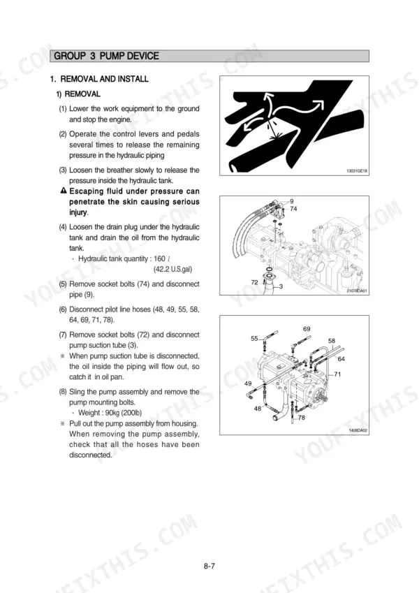
After installing the pump, remove the air vent plug (2EA) from the pump. Start the engine and run it at low idling until oil comes out from the plug, then tighten the plug fully. p. 329
Will this Hyundai R180LC-7A Service Manual download right away?
This is a 490-page searchable PDF ready for immediate download. Works on any device, so pull it up on your phone while you're under the hood. No shipping, no waiting.
Can I print just the pages I need from this Hyundai R180LC-7A manual?
Yes. Many mechanics print the section they need for their own shop and bring it to the bench.






Reviews
There are no reviews yet.