

Part of the JCB Repair Manuals.
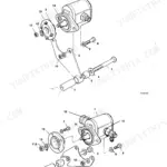
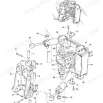
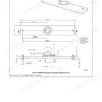
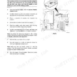
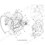
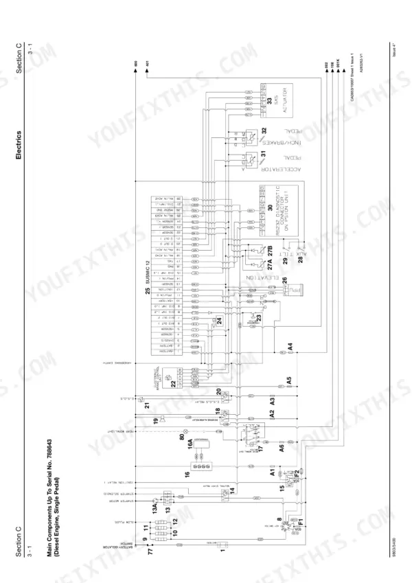
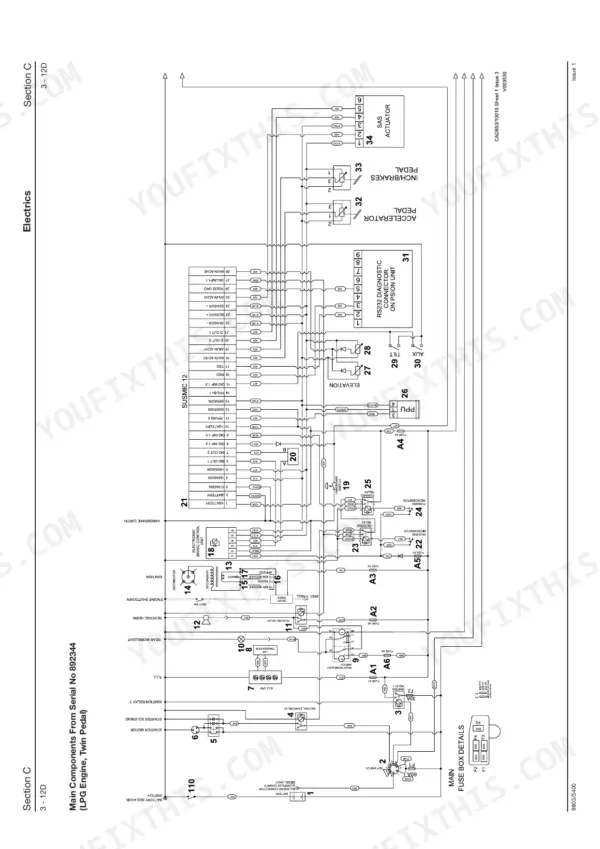
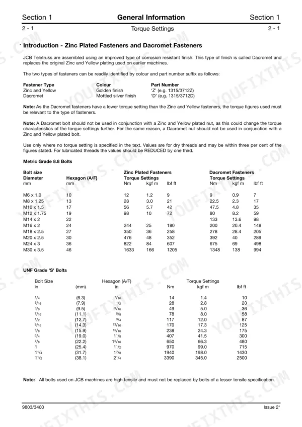
Covering everything from the intelligent transmission to the load moment indicator, this 609-page JCB Teletruk TLT25 service manual PDF (OEM #9803/3400 Issue 16) breaks down every system for your TLT25 Teletruk. Inside, you get massive wiring diagrams, complete hydraulic schematics detailing pressure tapping points, and step-by-step diagnostic procedures for the entire drivetrain. Open to the mechanical sections to find full exploded views of the steering unit and extensive torque tables for metric and UNF fasteners. Lock down the steering and main hydraulic pump securing bolts to exactly 79 Nm, and verify your wheel nuts are torqued to 150 Nm before returning the lift to the yard. Downtime kills your bottom line. Grab this bookmarked digital reference, load it onto your shop tablet, and start turning wrenches.
What's Inside This Manual
| System | Pages | Key Topics |
|---|---|---|
| General Information | 5-18 | Identification (Vehicle Identification Number, Unit Identification, Typical Engine Identification Number) |
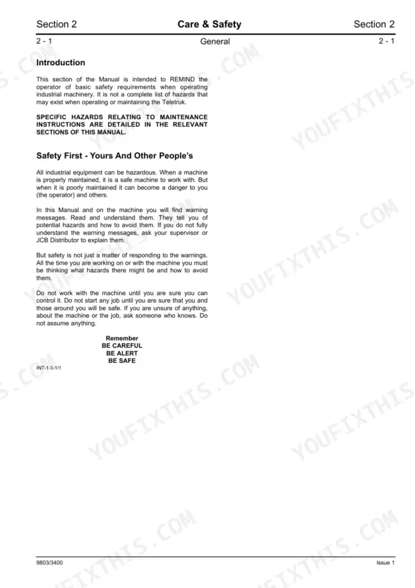
| Care & Safety | 19-26 | General Safety, Operating Safety, Maintenance Safety |
| Routine Maintenance | 27-54 | Fluids, Capacities and Lubricants, Service Schedules, Operator's Enclosure and Seat Belt, Cleaning the Machine, Greasing, Hydraulic System, Air Filter |
| Attachments | 55-64 | Hydraulic Hoses, Forks, Bucket, Quickhitch |
| Body & Framework | 65-86 | Access Procedures for Maintenance, Cab, Operator's Seat, Direct Glazing, Emergency Exit, Counterweight, Diesel Fuel Tank, Hydraulic Tank |
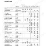
| Technical Data | 89-93 | |
| Test Methods | 94-95 | |
| Schematic | 96-164 | Electrical Power and Ignition, Starting System, Engine Management, Braking System, Transmission and Drive System |
| Battery | 165 | |
| Alternator | 166-167 | |
| Starter Motor | 168-169 | |
| Load Moment Indicator | 170-183 | Lmi Calibration, Test Weights, Fault Code Diagnostics, Psion Diagnostic Tool Interface |
| Harness Data | 184-378 | Wiring Harness Repair, Wire Identification, Wire Tracing, Mainframe Harness Connectors, Harness Diagrams |
| Controls | 379-472 | Torque Convertor Response (Tcr), Intelligent Transmission (It), Psion Diagnostic Tool, Sensor Calibration and Parameters, Speed Sensors |
| Hydraulics | 473-543 | Technical Data, Hydraulic Contamination, Schematics, Pressure Tapping Points, Descriptions, Oil Cooler, Pumps |
| Transmission | 544-575 | Moving a Disabled Machine, Wheels and Tyres, Start-Up, Drive Motors, Transmission Pump, Rear Axle, Spring Plunger Shimming Procedure |
| Brakes | 576-577 | Brake Pedal Removal and Replacement, Brake Pedal Potentiometer Adjustment, Brake Pressure Reducing Valve, Park Brake Dismantling, Park Brake Assembly, Park Brake Test |
| Steering | 578-589 | Hydraulic Steering Unit, Power Track Rod |
| Engine | 590-609 | Technical Data, Radiator, Diesel & Lpg Engine, Lpg Fuel System |
Quick Reference Specifications
| Specification | Value | Page |
|---|---|---|
| Wheel nuts torque | 150 Nm (110 lbf ft) | p. 549 |
| Steering/Main Hydraulic Pump securing bolts (B) | 79 Nm (58 lbf ft, 8 kgf m) | p. 512 |
| Steering/Main Hydraulic Pump securing bolts (E) | 90 Nm (66.5 lbf ft, 9 kgf m) | p. 512 |
| Hoses Screwed onto Adaptors (1/8” BSP) | 14 Nm (10 lbf ft) | p. 8 |
| Hoses Screwed onto Adaptors (1/4” BSP) | 24 Nm (18 lbf ft) | p. 8 |
| Electrolyte level in each cell | 6 mm (0.25 in.) above the plates | p. 38 |
| Specific Gravity at 15 °C (60 °F) - Fully Charged (Ambient temp up to 27 °C) | 1.270 - 1.290 | p. 165 |
| Wire splice dimension | 7mm | p. 184 |
| Drive Motors hydraulic connections | 44-50 Nm (33-37 lbf ft, 4.6-5.1 kgf m) | p. 553 |
| Drive Motors cap screw M10 x 30 | 56 Nm (42 lbf ft, 5.8 kgf m) | p. 553 |
| Air Filter inner element replacement interval | at least every third time the outer element is changed | p. 43 |
| Engine oil filter replacement interval (new engine) | after the first 50 operating hours | p. 592 |