
Part of the John Deere Repair Manuals.
This is the John Deere TM-1212 Technical Manual for the JD862 elevating scraper, 1214 pages covering the engine, transmission, torque converter, axles, steering, brakes, electrical system and the scraper and haulage device itself. The System Testing section (Section 90) carries a complete foldout Electrical Schematic and Wiring Diagram with numbered wires for harness tracing, plus a foldout Hydraulic Schematic covering the main hydraulic, elevator, bowl, ejector, steering and brake circuits. Component specifications, clearances and torque values are printed throughout, from engine crankshaft and camshaft fits to the bowl, ejector and sliding-floor cylinder specs and cutting-edge bolt torques.
What's Inside This John Deere JD862 Manual
| System | Pages | Key Topics |
|---|---|---|
| General Information | 3-78 | Specifications, Safety, Predelivery Service, Fuels and Lubricants, Alphabetical Index |
| Wheels | 79-86 | Powered and Non-Powered Wheels, Fastenings |
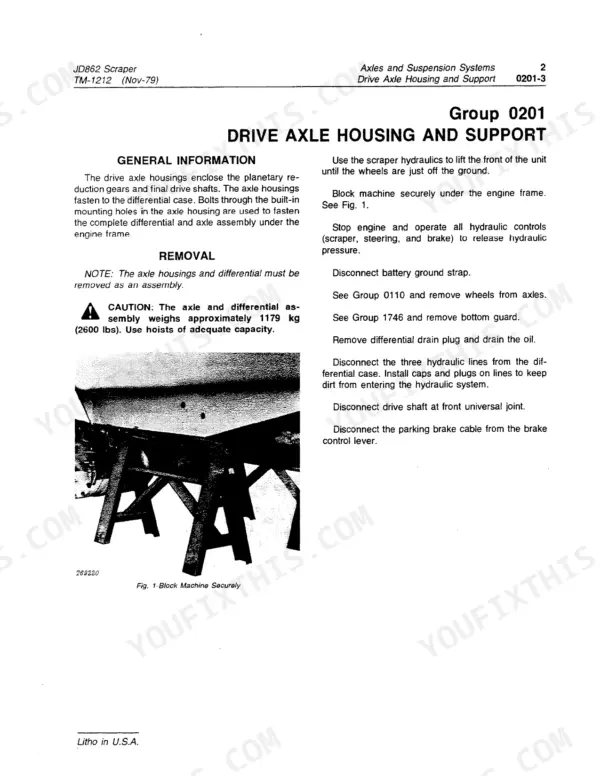
| Axles and Suspension Systems | 87-142 | Drive Axle Housing and Support, Differential or Bevel Drive, Non-Powered Wheel Axles, Reduction Gears |
| Transmission | 143-270 | Input Drive Shafts and U-Joints, Gears Shafts and Bearings, Power Shift Clutch, Hydraulic System |
| Engine | 271-438 | Removal and Installation, Crankshaft and Main Bearings, Camshaft and Valve Actuating Means, Cylinder Head and Valves, Cooling System |
| Engine Auxiliary Systems | 439-466 | Starting Aids, Cooling, Air Intake, Exhaust, Fuel Supply |
| Torque Converter | 467-512 | Housing, Turbine, Hydraulic System |
| Steering System | 513-546 | Hydraulic System, Steering Column, Steering Cylinders, Steering Metering Pump |
| Service Brakes | 547-572 | Service Brake Discs and Calipers, Hydraulic System |
| Parking-Emergency Brakes | 573-582 | Parking Brake, Emergency Brake Linkage |
| Miscellaneous Vehicle | 583-588 | Miscellaneous Vehicle Components |
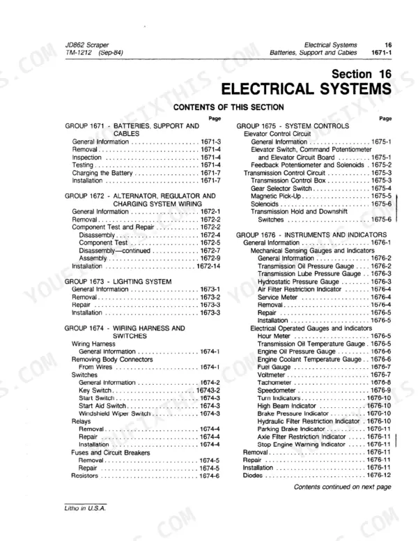
| Electrical System | 589-648 | Batteries Support and Cables, Alternator and Regulator, Lighting System, Wiring Harness and Switches, Instruments and Indicators |
| Frame, Chassis or Supporting Structure | 649-662 | Frame, Chassis and Supporting Structure |
| Operator's Station | 663-704 | Operator Enclosure, Seat and Seat Belt, Heating and Air Conditioning |
| Sheet Metal and Styling | 705-720 | Sheet Metal Panels and Styling |
| Safety, Convenience and Miscellaneous | 721-726 | Safety and Convenience Items |
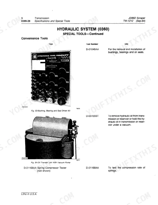
| Main Hydraulic System | 727-810 | Main Hydraulic Pump, Stroke Control Valve, Pressure Relief, Hydraulic Reservoir and Filters |
| Scraper and Haulage Device | 811-842 | Bowl Lift Cylinders, Ejector Gate Cylinder, Sliding Floor Cylinder, Cutting Edge and Side Cutter Bolts |
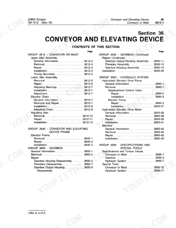
| Conveyor and Elevating Device | 843-934 | Conveyor Mast, Gear Box, Hydraulic System |
| System Testing | 935-1214 | Engine Testing, Electrical System Testing (Wiring Diagram, Electrical Schematic), Power Train Testing, Hydraulic System Testing (Hydraulic Schematic) |
Quick Reference Specifications
| Specification | Value | Page |
|---|---|---|
| All Models | ||
| Engine Gross Power | 270 hp (201 kW) | p. 17 |
| Engine Net Power | 250 hp (186 kW) | p. 17 |
| Bowl Capacity (SAE heaped) | 16 cu. yd. (12.23 m3) | p. 17 |
| Main Hydraulic System Pressure | 2350 psi (16 203 kPa) | p. 17 |
| Elevator System Pressure | 5000 psi (34 475 kPa) | p. 17 |
| Fuel Tank Capacity | 113 gal. (429 Liters) | p. 18 |
| Cooling System Capacity (Sep-84 revision) | 15 gal. (56.8 Liters) | p. 18 |
| Engine Slow Idle | 925 rpm | p. 33 |
| Engine Fast Idle | 2325 rpm | p. 33 |
| Cutting Edge Plow Bolts Torque | 407 N·m (300 lb-ft) | p. 837 |
| Bowl Lift Cylinder Stroke | 508 ± 3.0 mm (20.0 ± 0.12 in.) | p. 840 |
| Engine | ||
| Valve Clearance, Intake / Exhaust | 0.38 / 0.64 mm (0.015 / 0.025 in.) | p. 291 |
| Crankshaft | ||
| Main Bearing Cap Screws Torque | 278 to 292 N·m (205 to 215 lb-ft) | p. 287 |
John Deere JD862 Common Problems This Manual Covers
Bowl lift or ejector gate cylinders drift down and weep oil at the rod
Hard seals and worn rod guides do this on any 862 with hours on it. The Scraper and Haulage Device section covers removal, teardown, and seal and guide replacement for the bowl lift, ejector gate and sliding floor cylinders, and gives the 508 mm (20.0 in.) bowl lift stroke for checking travel afterward.
Manual Section: Scraper and Haulage Device p. 840Cutting edge and side cutter bolts work loose and edge wear takes off
A loose edge hammers its bolt holes oval and eats the mounting face fast. The Cutting Edge and Side Cutter Bolts coverage in the Scraper and Haulage Device section gives the plow bolt torque of 407 N·m (300 lb-ft) and the replacement procedure - retorque after the first hours back in the cut.
Manual Section: Scraper and Haulage Device p. 837Elevator chain slap, gear box whine, or flights stalling in sticky loads
Start with the Conveyor and Elevating Device section for the mast, gear box and elevator hydraulic system, then run the hydraulic tests in System Testing to confirm the 5000 psi elevator circuit is actually making pressure before you commit to tearing the gear box apart.
Manual Section: Conveyor and Elevating Device p. 17Engine runs hot pulling a full 16 yard bowl
The Engine section covers the cooling system itself, and Engine Auxiliary Systems handles the cooling, air intake and exhaust side. Engine Testing in the System Testing section lets you prove whether you have a cooling fault or an engine down on power against its 2325 rpm fast idle spec.
Manual Section: Engine p. 33Frequently Asked Questions
Does the JD862 TM-1212 manual include the electrical wiring diagram?
Yes. Section 90 (System Testing) ends with a foldout Electrical Schematic on page 1015. The page folds out and carries a numbered component legend keyed to the drawing - voltmeter, parking brake, elevator front and rear solenoids, elevator circuit board, feedback and command potentiometers and the rest of the machine's electrical devices. p. 1015
Is there a hydraulic schematic for the JD862's hydraulic system?
Yes. A foldout Hydraulic Schematic sits on page 1055, printed as part of the System Testing section, with its component legend on the facing page 1054 covering the main hydraulic pump, elevator pump, bowl, ejector and sliding floor circuits. p. 1055
What is the torque for the main hydraulic pump's stroke control valve housing?
Stroke Control Valve Housing-to-Pump is 40-68 N-m (30-50 lb-ft) for the initial tightening and 115 N-m (85 lb-ft) final. The Resonator Plug torques to 136 N-m (100 lb-ft), the Diagnostic Port Plug to 34 N-m (25 lb-ft), and the Solenoid Valve (if used) to 20 N-m (15 lb-ft). p. 802
What are the JD862's main and elevator hydraulic system operating pressures?
The Main Hydraulic System operates at 2350 psi (16 203 kPa) and the Elevator System at 5000 psi (34 475 kPa), per the manual's general specifications table. p. 17
What is the bolt torque for the JD862's bowl cutting edge and side cutters?
Cutting edge plow bolts (34 used) torque to 407 N-m (300 lb-ft), and side cutter plow bolts (8 used) torque to 339 N-m (250 lb-ft). p. 837
What are the bore and stroke specs for the JD862's bowl lift and ejector gate cylinders?
Bowl Lift Cylinder: bore 126.24 +/- 0.25 mm (4.970 in.), stroke 508 +/- 3.0 mm (20.0 in.). Ejector Gate Cylinder: bore 75.64 +/- 0.13 mm (2.978 in.), stroke 1130.3 +/- 3.0 mm (44.50 in.). Both rod guides torque to 339-407 N-m (250-300 lb-ft). p. 840







Reviews
There are no reviews yet.