
Part of the Kubota Repair Manuals.
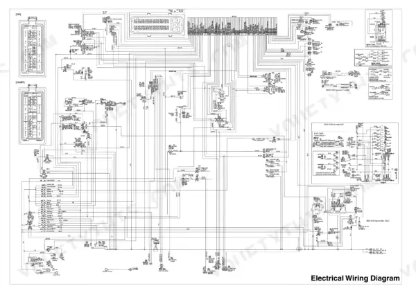
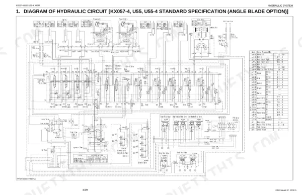
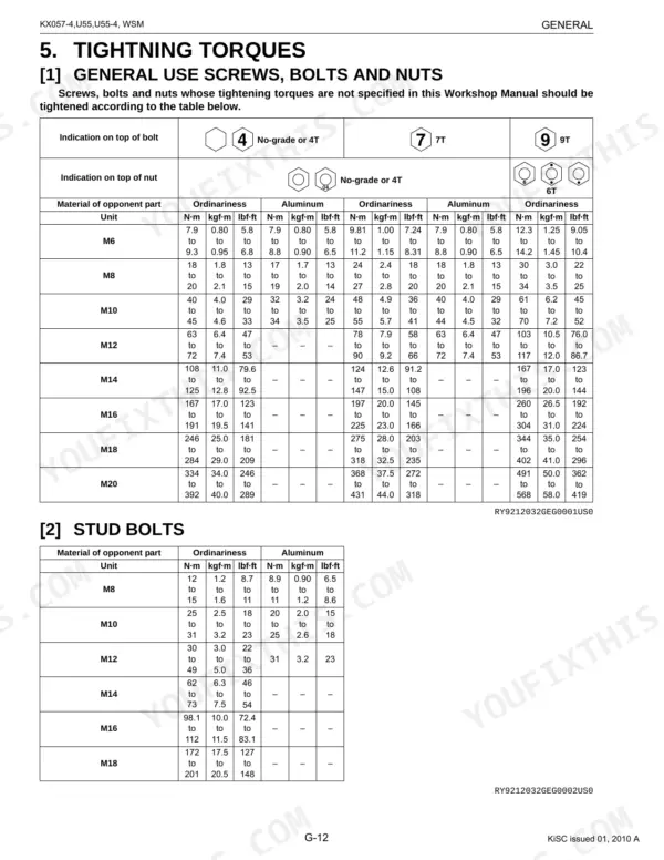
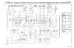
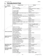
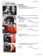
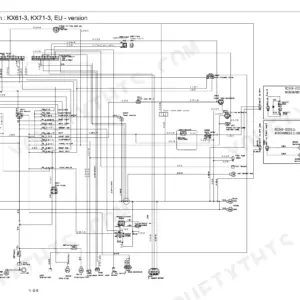
This 739-page Kubota KX057-4, U55 service manual PDF (factory number RY911-20510) covers the KX057-4 and U55-4 excavators. The hydraulic circuit diagram maps the pump, control valve, swivel motor and travel motor circuits, and the hose routing drawings show where each line runs out to the boom, arm and blade cylinders. Wiring circuits, meter panel troubleshooting and pilot valve rebuilds for control, travel, swing and blade follow, plus device performance measurement so you confirm the numbers before handing the machine over. Spin the return filter on to 68.6 to 78.4 N·m; a 1/2 hose union nut takes 58.8 to 63.7 N·m. Chapter bookmarks and a searchable text layer land you on the travel motor or refrigerant section in seconds.
What's Inside This Kubota KX057-4, U55, U55-4 Manual
| System | Pages | Key Topics |
|---|---|---|
| Information | 6-22 | Safety First, Safety Decals |
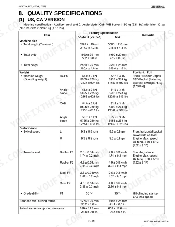
| General | 23-76 | Checking Bachoe Identification, Engine Identification, Handring Precautions for Electrical Parts and Wiring, Tightning Torques, New Product Feature, New Features Outline |
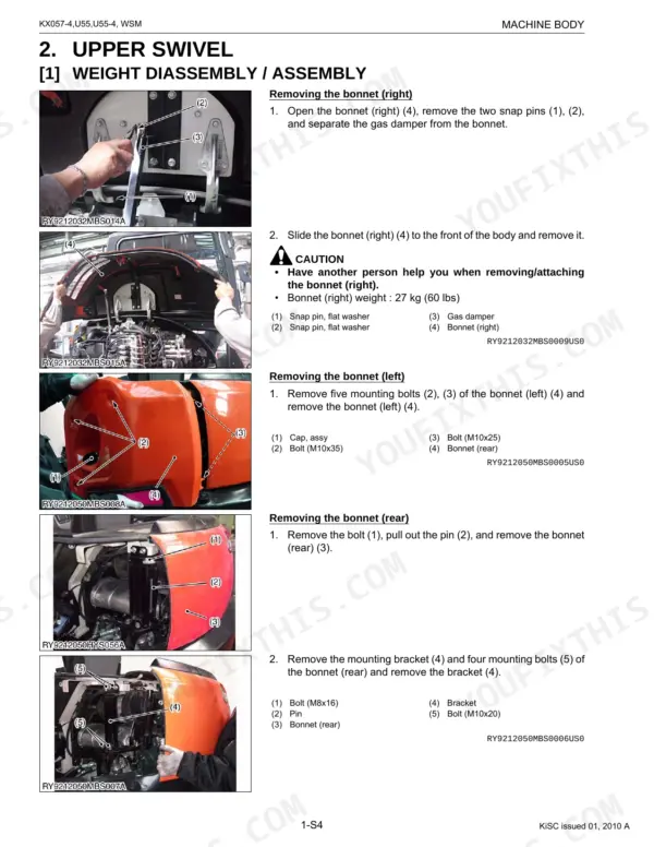
| Machine Body | 77-117 | Front Operating Machine, Upper Swivel, Chassis |
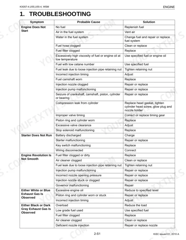
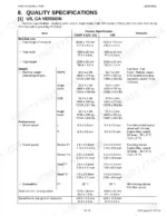
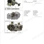
| Engine | 118-227 | Engine Specifications, Special Tools, Troubleshooting, Servicing Specifications |
| Hydraulic System | 228-510 | Diagram of Hydraulic Circuit, Hydraulic Device Layout, Features, Pump, Control Valve, Swivel Motor, Travel Motor, Hydraulic Cylinder |
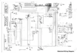
| Electrical System | 511-661 | Electronic Device Layout, Wiring Circuit, Troubleshooting, Inspections, Meter Panel Operation Procedures |
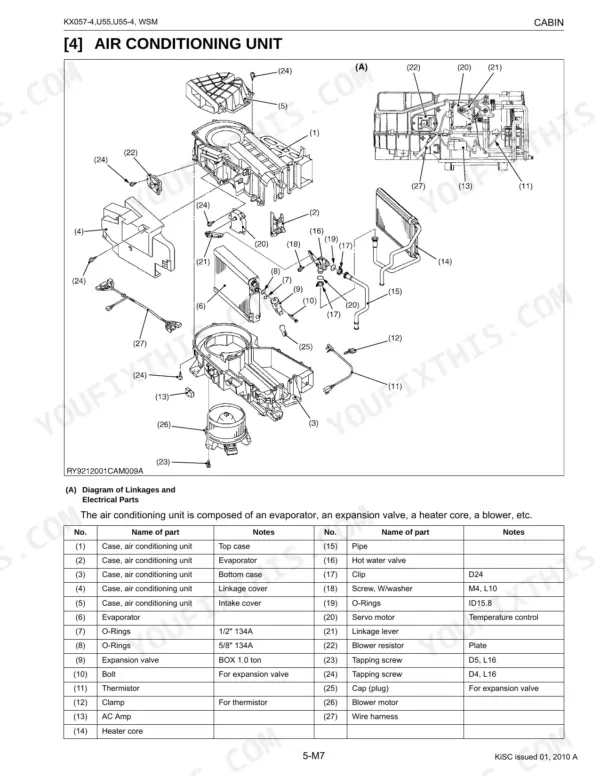
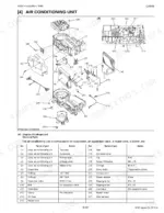
| Cabin | 662-739 | Air Conditioning System, Wiper, Troubleshooting, Maintenance and Service Related Specifications, Torque, Precautions When Repairing the Refrigerant System |
Quick Reference Specifications
| Specification | Value | Page |
|---|---|---|
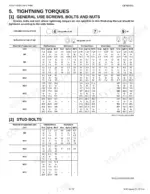
| Torque for Hydraulic Hose Fittings (Union Nuts) | 7.8 to 11.8 N·m (1/8), 24.5 to 29.2 N·m (1/4), 37.2 to 42.1 N·m (3/8), 58.8 to 63.7 N·m (1/2), 117.6 to 127.4 N·m (3/4), 181.3 to 191.1 N·m (1), 220.5 to 230.3 N·m (1-1/4) | p. 37 |
| Torque for Hydraulic Hose Fittings (Tapered Nuts) | 19.6 to 29.4 N·m (1/8), 36.6 to 44.1 N·m (1/4), 68.6 to 73.5 N·m (3/8), 83.4 to 88.3 N·m (1/2), 166.6 to 181.3 N·m (3/4) | p. 37 |
| Tightening torque for filter (return) | 68.6 to 78.4 N·m | p. 90 |
| Tightening torque for nut (2) (suction filter) | 16 to 24 N·m | p. 91 |
| Tightening torque Bolt (3) | 123.6 to 147.1 N·m, 12.6 to 15.0 kgf·m, 91.17 to 108.4 lbf·ft | p. 97 |
| Oil cooler joint screw torque | 64 to 73 N·m (6.5 to 7.5 kgf·m, 47 to 54 lbf·ft) | p. 194 |
| Tightening torque for bolt (25) (hydraulic oil tank) | 77.5 to 90.2 N·m | p. 89 |
| Tightening torque for bolts (a) (b) (c) (d) (anti vibration support) | 77.5 to 90.2 N·m | p. 93 |
| AUX2 port MAX. flow volume (Theoretical) | 37 L/min (9.87 U.S.gal/min) | p. 549 |
| AUX1 port MAX. flow volume (Theoretical) | 75 L/min (20 U.S.gal/min) | p. 549 |
| Engine Oil Capacity (Crankcase) | 9.0 L | p. 66 |
Kubota KX057-4, U55, U55-4 Common Problems This Manual Covers
Kubota KX057-4 all front operations slow or not moving with entire hydraulic system low on power
Check hydraulic tank oil level and oil quality first, then replenish or change the oil as page 507 directs. Inspect the suction filter and pilot filter for blockage. Measure pilot primary pressure, then main relief valve pressure: P1 and P2 should read 285 ± 5.1 kgf/cm2 per page 51. Release the pressure before you disconnect any hydraulic line, and tighten all connections before you apply pressure (page 9). If pressures are good, inspect the LS regulator spool and pump coupling.
Manual Section: Hydraulic System Troubleshooting p. 507One front cylinder only moves slow, will not move, or drifts with major leak volume
Measure pilot secondary pressure of the applicable cylinder following page 508; disassemble, clean or replace the pilot valve if it reads low. Inspect that cylinder's overload relief valve and wash the seat surface or replace it. Check the control valve spool for sticking and wash it. If drift persists, disassemble the cylinder and replace the seals, releasing the pressure before you disconnect its hydraulic lines (page 9).
Manual Section: Hydraulic System Troubleshooting p. 508Travel slow on one side, machine meanders, or one track will not travel at all
Clean packed earth from around the crawler and check crawler tension first, following page 509. Measure travel pilot valve secondary pressure and the slow side travel relief pressure. Inspect the travel motor counterbalance spool and measure travel motor drain volume. To test the swivel joint, remove its travel outlet hose, plug it and measure relief pressure; release the pressure before you disconnect that hose and tighten connections before you apply pressure (page 9).
Manual Section: Hydraulic System Troubleshooting p. 509Swivel speed low, no swivel at all from the pilot valve, or swivel drift
Check that the pilot valve spool returns to neutral, then inspect the control valve swivel section spool for sticking and clean it, following page 510. Measure swivel relief pressure; before you start, make sure no persons or obstacles are within the swivel range (page 502). Measure swivel motor drain volume, inspect the parking brake friction plate for snagging, and check the make-up poppet if it drifts.
Manual Section: Hydraulic System Troubleshooting p. 510Radiator net and radiator fin clogged with dust, engine overheats during work
Let the engine cool before you start; never remove the radiator cap while the engine runs or right after it stops, and loosen it slowly to release pressure (pages 8 and 9). Check coolant and replenish, clean the radiator net and fins, and inspect the fan belt for breakage or stretch. Check engine oil level (crankcase holds 9.0 L per page 66) and the radiator cap, following page 155.
Manual Section: Engine Troubleshooting p. 155Engine does not start with Wrong Key or Lift the lever message on the display
Start the engine with the registered key if Wrong Key shows, and lift the unload lever if Lift the lever appears, following page 526. Check slow-blow and other fuses, and never fit a fuse of higher capacity (page 529). Tighten GND wire bolts, check battery voltage and specific gravity, then measure voltage at starter terminals B and S. Never short across the starter terminals (page 8).
Manual Section: Electrical System Troubleshooting (Start-up Equipment) p. 526Frequently Asked Questions
How do I reset the periodic check guidance on the meter panel?
The periodic check guidance can be reset by turning the key ON/OFF ten times for the automatic method, or by pressing "Yes" on the periodical check screen when the message "Have you finished the periodical check?" appears for the manual method. p. 583
How do I bleed air from the hydraulic system after replacing hoses?
To bleed air from the hydraulic system, connect a vacuum pump to the breather hose of the hydraulic tank and apply vacuum pressure. Then, operate each control lever for the boom, arm, bucket, and swivel to full stroke, and operate the travel lever, blade lever, swing pedal, standby pedal, and service port pedal each to full stroke. p. 496
What is the procedure for bleeding air from the piston pump?
After operating, with the engine stopped, remove the hose at the top of the pump, insert a hexagonal plug, and pull it out. Drape the hose on the front of the weight for 30 seconds. Then, start and idle the engine, checking for cavitation noise, and repeat until the noise subsides. Finally, raise the engine speed to 1500 rpm, then 2000 rpm, and finally maximum rpm, operating the arm slowly to check for cavitation. p. 495
What is the tightening torque for the cylinder head mounting screws on the Kubota KX057-4, U55, U55-4?
The tightening torque for the cylinder head mounting screws is 147 to 156 N·m (15.0 to 16.0 kgf·m, 109 to 115 lbf·ft). p. 181
What is the specified valve clearance for the engine on the Kubota KX057-4, U55, U55-4?
The valve clearance for the engine when cold is 0.13 to 0.17 mm (0.0052 to 0.0066 in.). p. 167
How is this Kubota KX057-4 Service Manual delivered?
A 739-page Service Manual in searchable PDF format, available the moment you complete checkout. View on computer, tablet, or phone, with no shipping wait.
Am I free to print this Kubota KX057-4 Service Manual?
You can. Print the sections you want for your own use and keep the file as your backup.




Reviews
There are no reviews yet.