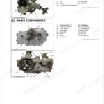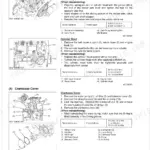

Part of the Kubota Repair Manuals.
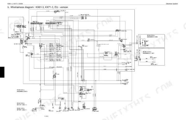
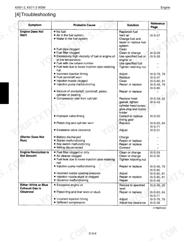
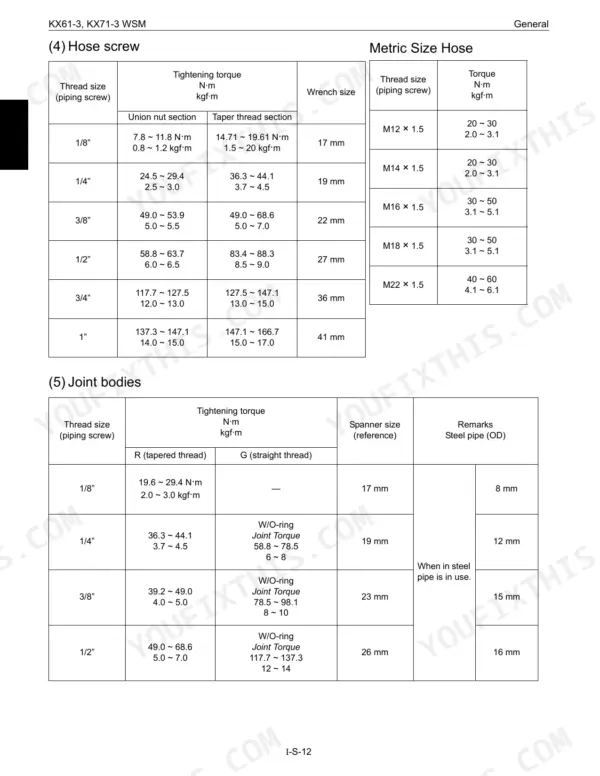
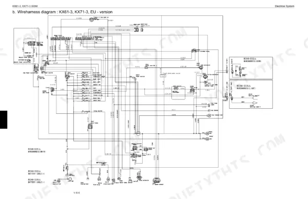
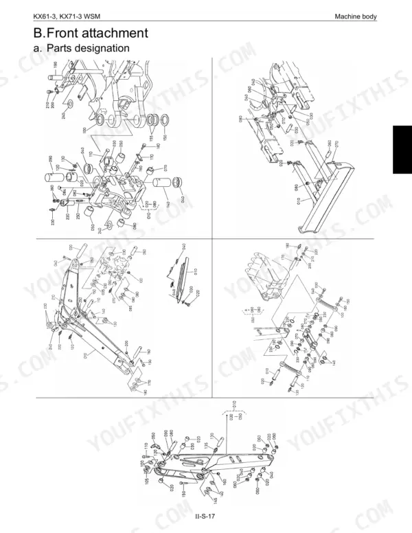
Before you crack a fitting on the boom cylinder or tee a gauge into the pump line this afternoon, the Kubota KX61-3, KX71-3 service manual PDF (Kubota part 97899-61050) puts 458 factory pages for both compact excavators on your screen. Hydraulic work takes up close to half the book: pump flow and pressure measurement tests, swivel motor and reduction gear teardown, pilot valve and TPSS valve rebuilds, and hose routing lists that trace each pilot, high pressure, suction and return line back to the tank. Wire harness diagrams, coupler layouts and circuit tests close out the book. Retire a front attachment pin once it wears 1.0 mm under size, and bring a 1/2-inch hose union nut to 58.8 to 63.7 N·m. A swivel motor rebuild can sit half done over one missing figure. Bookmarked and text searchable, this copy finds that number fast, so your machine is back on its tracks and digging.
What's Inside This Manual
| System | Pages | Key Topics |
|---|---|---|
| General | 5-24 | Body and Engine Identification Marks, Safety Precautions for Servicing |
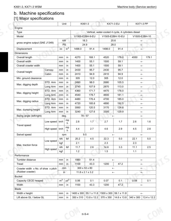
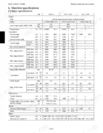
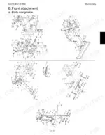
| Machine Body | 25-92 | Specifications, Front Attachment, Cab Canopy Installation, Under Carriage |
| Engine | 93-226 | Engine Accessories, Engine Dismounting and Remounting, Engine Mechanism, Engine Service |
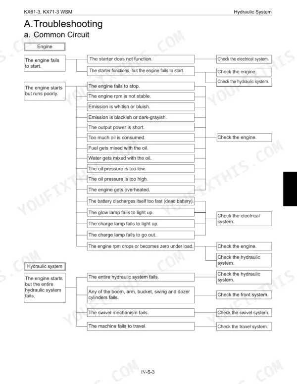
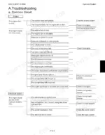
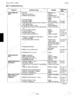
| Troubleshooting | 227-240 | Common Circuit, Hydraulic System, Pump, Motor, Swivel Performance, Traveling Performance |
| Specifications | 241-269 | Pump Specifications, Control Valve, Swivel Performance, Traveling Performance, Cylinder Speed, Natural Fall |
| Testing | 270-306 | Pump Flow, Pressure Measurement, Operating Speed, Cylinder Natural Fall, Lever Operating Force, Lever Stroke |
| Disassembling and Assembling - Front Attachment and Pump | 307-342 | Front Attachment Assembly, Pump Dismounting, Pump Reassembling, Control Valve, Pilot Valve |
| Disassembling and Assembling - Swivel Motor and Reduction Gear | 343-376 | Swivel Motor Disassembling, Swivel Motor Reassembling, Reduction Gear Case, Bearing Replacement, Oil Seal |
| Disassembling and Assembling - Cylinder and Valves | 377-403 | Boom Cylinder, Pilot Filter, Change Valve, TPSS Valve |
| Hydraulic Tank and Hose Routing | 404-424 | Hydraulic Oil Tank, Pilot Hose List, High Pressure Hose, Suction Hose Route, Return Drain Hose |
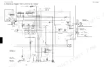
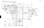
| Electrical System | 425-458 | Wireharness Diagram and Couplers, Troubleshooting and Testing, Wire Harness Installation |
Quick Reference Specifications
| Specification | Value | Page |
|---|---|---|
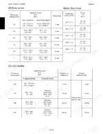
| Hose screw union nut section (1/8") | 7.8 ~ 11.8 N·m | p. 16 |
| Hose screw union nut section (1/4") | 24.5 ~ 29.4 N·m | p. 16 |
| Service limit of pin dia. | -1.0 mm (-0.04 in.) | p. 31 |
| Service limit of front bushing | +1.0 mm (+0.04 in.) | p. 32 |
| Bucket link clearance | 0.6mm | p. 47 |
| Fan belt deflection | 10 to 12 mm (0.394 to 0.472 in.) | p. 97 |
| Injection nozzle pressure | 13.73 to 14.71 MPa (140 to 150 kgf/cm², 1991 to 2133 psi) | p. 134 |
| Air filter element cleaning air pressure | 690 kPa (7 kgf/cm², 100 psi) | p. 163 |
| Fan belt tensioning force | 98 N (10 kgf, 22 lbs) | p. 162 |
| Swivel motor brake valve setting pressure | 17.7 MPa (180.00 kgf/cm²) | p. 249 |
| Swivel motor brake valve cracking pressure | 15.7 MPa (160.00 kgf/cm²) | p. 249 |
| Slow-blow fuse | 50A | p. 433 |