Part of the Kubota Repair Manuals.
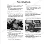
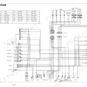
Brake trouble, a transaxle fault or a front axle problem each has its own troubleshooting section in this 333-page Kubota GR2120 service manual PDF, written for the GR2120 and GR2120-AU lawn tractors. Wiring diagrams trace the tractor's electrical circuits, while hydraulic schematics follow the hydraulic circuit through the steering controller and the mower lift cylinder. Engine, brake and front axle chapters carry their own servicing specifications, and the general chapter lists lubricants, special tools and the maintenance check list. Replace the fuel filter element every 200 hrs. Check the fuel lines every 6 months, and torque the cylinder head screws to 38 to 42 N-m. If you are setting front wheel alignment or adjusting the brake pedal, each job has its own chapter. Download the PDF, use the bookmarks to reach the PTO clutch or mower blade maintenance pages, and search the text layer when you need a spec by name.
What's Inside This Manual
| System | Pages | Key Topics |
|---|---|---|
| Safety First | 6-8 | Before You Start Service, Operate Safely |
| Safety Decals | 9-11 | Care of Danger Warning and Caution Labels |
| Specifications | 12-13 | Engine Specifications |
| General | 15-80 | Identification, General Precautions, Lubricants, Maintenance Check List, Special Tools, Implement Limitations |
| Engine | 81-139 | Engine Body, Lubricating System, Cooling System, Fuel System, Troubleshooting, Servicing Specifications |
| Transaxle | 140-206 | Travelling System, Hydraulic Transmission, Glide Steer Section, Front Wheel Drive, PTO Clutch, Troubleshooting |
| Brakes | 207-219 | Brake Mechanism, Troubleshooting, Servicing Specifications, Brake Pedal Adjustment, Brake Assembly |
| Front Axle | 220-237 | Front Axle Structure, Troubleshooting, Servicing Specifications, Front Wheel Alignment, Differential Gear Assembly |
| Steering, Hydraulic System, and Mower | 238-333 | Steering Controller, Hydraulic Circuit, Mower Lift Cylinder, Mower Linkage, Power Transmission, Mower Blade Maintenance |
Quick Reference Specifications
| Specification | Value | Page |
|---|---|---|
| Fuel filter element replacement interval | every 200 hrs | p. 28 |
| Fuel line check interval | every 6 months | p. 28 |
| Cylinder head screw | 38 to 42 N-m | p. 97 |
| Main bearing case screw 2 | 27 to 30 N-m | p. 122 |
| Glide Steer angle | 0.35 rad (22°) | p. 171 |
| Rear shaft nut torque | 40 N·m (4.1 kgf·m, 30 lbf·ft) | p. 162 |
| Brake assembly mounting bolt torque | 7.8 to 8.8 N-m (0.80 to 0.89 kgf-m, 5.8 to 6.4 lbf-ft) | p. 162 |
| Hydraulic PTO clutch assembly mounting bolt | 18 to 20 N·m | p. 187 |
| PTO clutch piston lock nut | 9.8 to 11 N·m | p. 162 |
| Center section mounting hex. socket head screw | 18 to 20 N·m | p. 185 |
| By-pass valve plug | 15.0 N·m | p. 185 |
| Brake Pedal Free Travel | 15 to 25 mm (0.59 to 0.98 in.) | p. 212 |