

Part of the New Holland Repair Manuals.
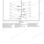
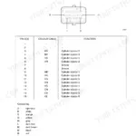
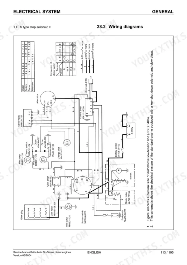
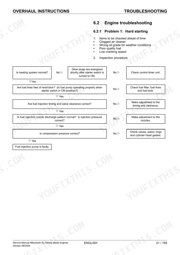
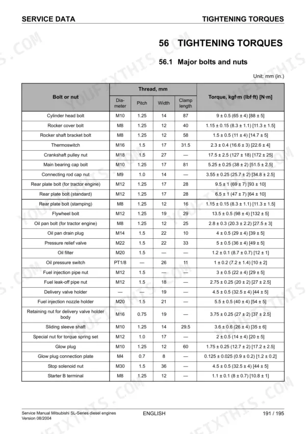
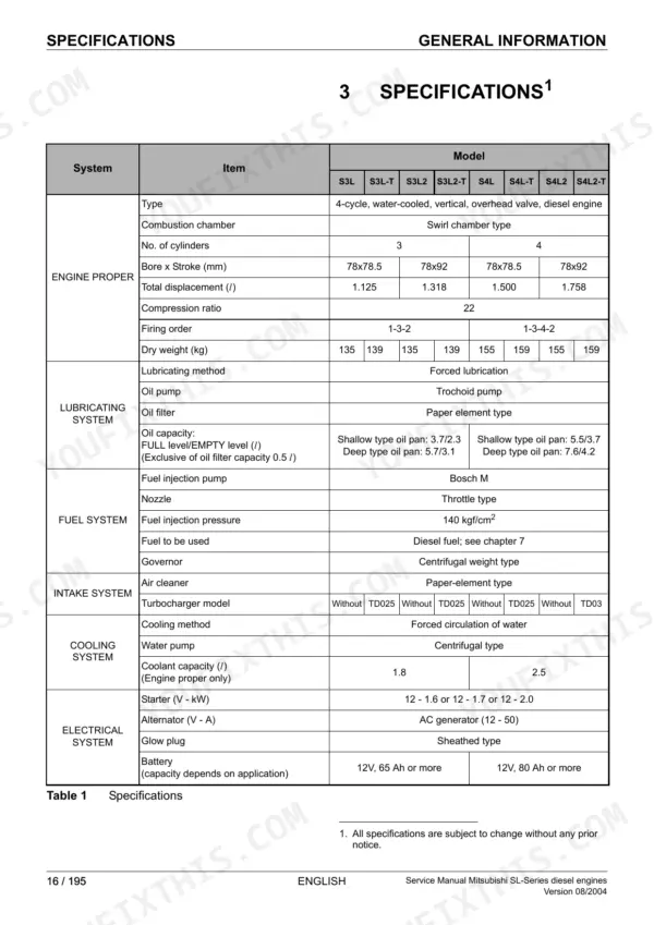
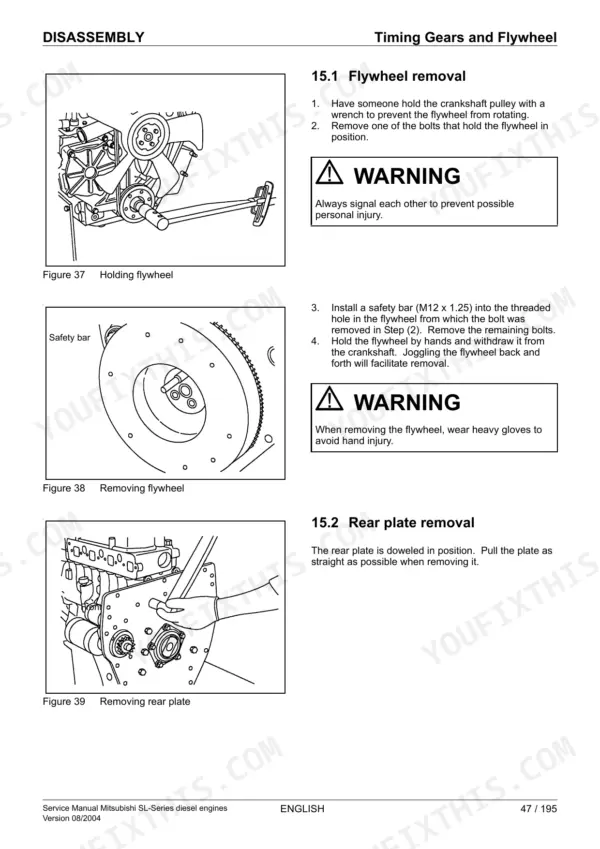
This 195-page Mitsubishi S3L Service Manual covers the whole diesel engine family: S3L, S3L-T, S3L2, S3L2-T, S4L, S4L-T, S4L2, and S4L2-T, so whichever variant sits in your machine, you're covered. Inside you get wiring diagrams for chasing electrical gremlins, exploded views for parts orientation during teardown, and a full troubleshooting section that walks through symptoms instead of leaving you guessing. You also get component location guides broken out by model, so you're not hunting for the fuel filter on an S4L-T using S3L pictures. Check the fuel injection nozzle holder torque at 5.5 kgf-m (54 N-m) and swap the fuel filter element every 500 hours, cartridge type every 400. No more calling around for a spec some parts counter guy half-remembers. Bookmarked and searchable, so you jump straight to your engine's section and get back to the shop floor.
Other edition of this manual
What's Inside This Manual
| System | Pages | Key Topics |
|---|---|---|
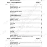
| General Information & Specifications | 10-17 | Model Identification, Serial Number Location, Component Location (S3L/S3L2, S4L/S4L2, Turbo Variants), Engine Specifications |
| Overhaul Assessment & Troubleshooting | 18-31 | Determining When to Overhaul, Compression Pressure Measurement, Engine Troubleshooting, Starting System Troubleshooting, Disassembly and Assembly Precautions |
| Engine Disassembly | 32-57 | Oil and Coolant Draining, Electrical Component Removal, Cooling and Fuel System Removal, Lubrication and Air Intake Removal, Cylinder Head and Valve Mechanism, Timing Gears and Flywheel, Cylinder Block, Crankshaft, Pistons and Oil Pan |
| Component Inspection | 58-81 | Cylinder Head and Valve Mechanism, Timing Gears and Flywheel, Cylinder Block, Crankshaft, Pistons and Oil Pan |
| Engine Assembly | 82-111 | Cylinder Block, Crankshaft, Pistons and Oil Pan, Timing Gears and Flywheel, Cylinder Head and Valve Mechanism, Air Inlet and Exhaust, Fuel, Lubrication, Cooling and Electrical Reassembly |
| Electrical System | 112-135 | Starter, Alternator, Key Shutoff System (Ets and Etr Solenoid Types), Automatic Glow System |
| Cooling System | 136-141 | General, Inspection, Thermostat, Water Pump |
| Lubrication System | 142-145 | General, Inspection, Oil Pump, Pressure Relief Valve |
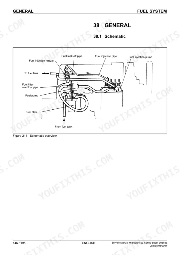
| Fuel System | 146-165 | Fuel Injection Nozzle, Fuel Injection Pump, Governor, Fuel Pump, Fuel Filter |
| Air Inlet & Exhaust System | 166-169 | General, Inspection, Exhaust Manifold, Air Inlet Cover |
| Servicing & Maintenance | 170-185 | Lubrication and Maintenance Chart, Engine Oil and Filter, Valve Clearance, Fuel Injection Timing, Fuel System Priming, Idle RPM Setting, Fuel Injection Nozzles, Fan Belt |
| Specifications, Torques & Tools | 186-195 | Specifications, Tightening Torques, Sealants, Special Tools |
Quick Reference Specifications
| Specification | Value | Page |
|---|---|---|
| Oil pressure switch closing pressure (indicator light comes on) | 0.5 ± 0.1 kgf/cm² (7 ± 1.4 psi) [49 ± 10 kPa] | p. 188 |
| Fuel filter element replacement interval | Every 500 service hours | p. 163 |
| Cartridge type fuel filter replacement interval | Every 400 service hours | p. 163 |
| Fuel injection nozzle holder tightening torque | 5.5 ± 0.5 kgf·m (40 ± 4 lbf·ft) [54 ± 5 N·m] | p. 183 |
| Thermostat temperature at which valve starts opening | 82 ± 1.5°C (180 ± 2.7°F) | p. 136 |
| Thermostat temperature at which valve lift is 8 mm (0.3 in.) | 95°C (203°F) | p. 136 |
| Fan belt deflection under 10 kgf (22 lbf) [98 N] force | 10 to 12 mm (0.4 to 0.5 in.) | p. 184 |
| Cylinder head bolt tightening torque | 9 ± 0.5 kgf·m (65 ± 4 lbf·ft) [88 ± 5 N·m] | p. 191 |
| Clearance between idler gear and shaft Standard | 0.03 to 0.07 (0.001 2 to 0.002 8) | p. 69 |
| Clearance between idler gear and shaft Limit | 0.20 (0.007 9) | p. 69 |
| Ambient temperature difference from normal coolant temperature (thermostat fully open) requiring investigation | More than 60°C (108°F) | p. 23 |