Part of the New Holland Repair Manuals.
Stamped on the block, the engine number tells you which of these you have: F3DE3684A, F3DE3684B, F3DFA613A, F3DFA613B, F3DFE613A or F3DFE613B, including the *E001, *E002, *A001 and *A002 build variants. All of them are covered here, in New Holland publication 84474511.
These are 135 mm bore, 150 mm stroke engines displacing 12880 cm³, and the manual works at that level: crankshaft and cylinder block across pages 58 to 122, cylinder head and valve assembly from 123, fuel and injection with the high pressure common rail from 142, then air intake and exhaust, cooling, lubrication and starting through page 253.
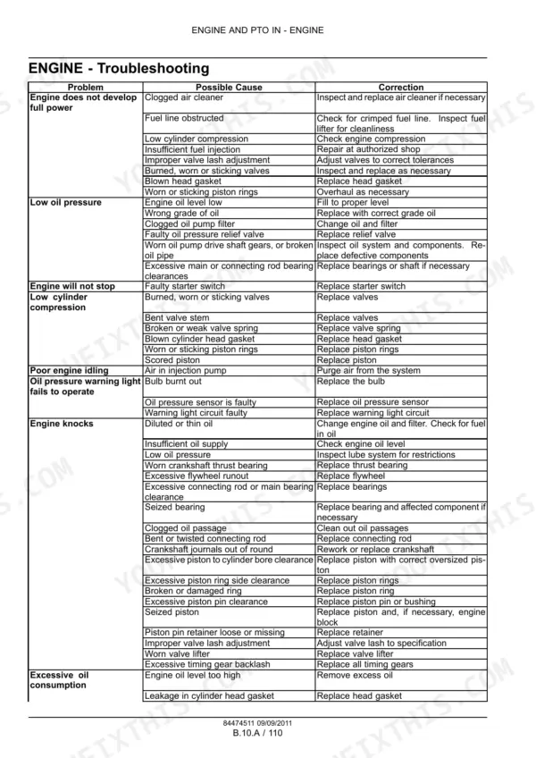
Guessing a torque or a running pressure on an engine this size costs you a bearing or a head gasket. The figures are printed here instead: cold valve lash, injector calibration pressure, oil pressure at idle and at peak rpm, thermostat opening range. It is a 255 page PDF, so it travels to the bench or the stand with you.
What's Inside This New Holland F3DE / F3DF Tier 4a Engine Manual
| System | Pages | Key Topics |
|---|---|---|
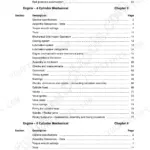
| Introduction | 4-21 | Ecology and the Environment, Safety Rules, Important Notice Regarding Equipment Servicing, How to Use and Navigate Through This Manual, Shop and Assembly |
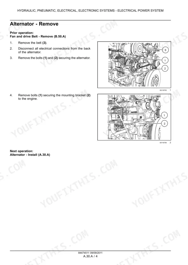
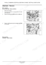
| Hydraulic, Pneumatic, Electrical, Electronic Systems | 22-27 | Electrical Power System |
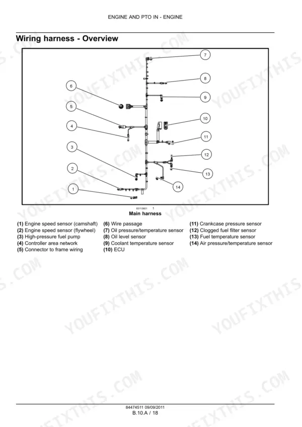
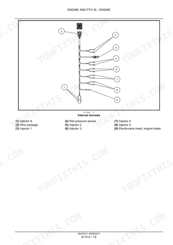
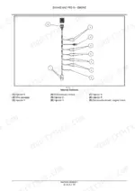
| Engine General Information and Specifications | 28-38 | Engine Specifications, Service Limits, Engine Overview, Wiring Harness |
| Valve Drive and Timing Gear | 39-46 | Rocker Assembly, Camshaft, Timing Gear, Idler Gear |
| Electronic Control and Sensing Systems | 47-57 | Control Module, EDC Pin Out, Flywheel Speed Sensor, Camshaft Speed Sensor |
| Crankshaft and Cylinder Block | 58-122 | Top Dead Center, Crankshaft Removal, Main Bearings, Cylinder Liners, Under Block Installation |
| Cylinder Head and Valve Assembly | 123-141 | Cylinder Head Removal, Valve Guide Replacement, Valve Seat Replacement, Valve Assembly |
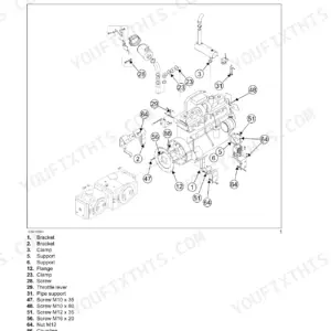
| Fuel and Injection System | 142-169 | Fuel Injection Pump, Fuel Injectors, High Pressure Common Rail, Fuel Lines |
| Air Intake and Exhaust Systems | 170-205 | Turbocharger, Air Cooler, Air Intake Manifold, Exhaust Manifold, Selective Catalytic Reduction |
| Cooling, Lubrication, and Starting Systems | 206-253 | Engine Coolant System, Thermostat, Water Pump, Lubrication System, Oil Pump, Oil Filter, Starting System |
Quick Reference Specifications
| Specification | Value | Page |
|---|---|---|
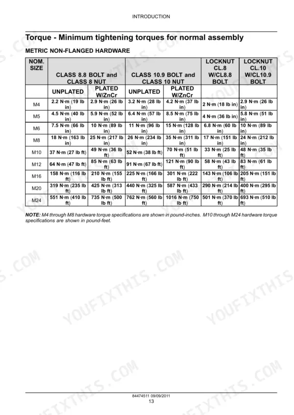
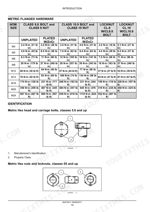
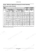
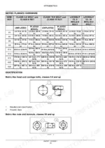
| Metric Flanged Hardware M4 Class 8.8 Bolt and Class 8 Nut Unplated | 2.4 N·m | p. 17 |
| Metric Flanged Hardware M4 Class 8.8 Bolt and Class 8 Nut Plated W/ZnCr | 3.2 N·m | p. 16 |
| Oil Pressure (Warm engine) - Idling | 3 bar (43.5 psi) | p. 32 |
| Oil Pressure (Warm engine) - Peak RPM | 4.5 bar (65.3 psi) | p. 32 |
| Flywheel speed sensor Max. tightening torque | 8 N·m (5.9 lb ft +/- ) 2 N·m (1.5 lb ft) | p. 54 |
| Camshaft speed sensor Max. tightening torque | 8 N·m (5.9 lb ft +/- ) 2 N·m (1.5 lb ft) | p. 55 |
| Fuel filter head bolt torque | 34 - 40 N·m (25 - 30 lb ft) | p. 160 |
| Maximum back pressure from fixed geometry turbo at rated power | Less than or equal to 25 kPa (4 psi) | p. 173 |
| Maximum exhaust gas temperature at rated power | 500 °C (932 °F) | p. 173 |
| Maximum pressure | 350 kPa (51 psi) relative | p. 173 |
| Maximum temperature | 200 °C (392 °F) | p. 173 |
| Oil filter tightening torque | 60 N·m (44.3 lb ft) ± 5 N·m (3.7 lb ft) | p. 224 |