

Part of the New Holland Repair Manuals.
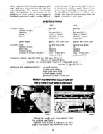
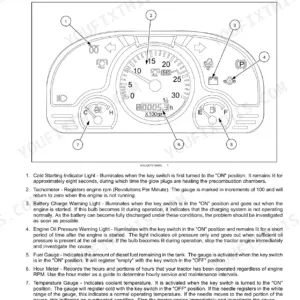
A walker bearing that lets go in mid harvest parks the whole combine, and that failure is why this New Holland 1400, 1500 service manual PDF exists: 190 pages of factory shop instruction for both models, issued under OEM ID 40481300. Hydraulic schematics trace oil from the main pump through the steering hand pump and the three spool control valve, and wiring diagrams map the electrical system down to the battery circuit. Teardown procedures run from the stone trap and concave clear back through the straw walkers, clutch, transmission, and unloading auger gearbox. Set the cylinder to concave clearance between 1 mm and 35 mm, then torque the rasp bar nuts to 10.3 kgm (75 lb.-ft.) before you close it up. Threshing losses never pick a convenient week. Print the pages you need; the bench copy can take the grease while the bookmarked, text searchable file stays clean on your shop computer between seasons.
What's Inside This New Holland 1400, 1500 Manual
| System | Pages | Key Topics |
|---|---|---|
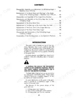
| Cylinder and Concave Area | 4-11 | Removal and Installation of the Stone Trap and Concave, Removal and Installation of the Cylinder |
| Beater Area | 12-15 | Removal of the Beater and Beater Shaft |
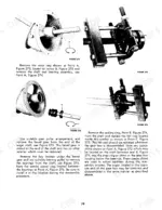
| Intermediate Shaft Area | 16-34 | Replacement of the Intermediate Shaft Left-Hand Bearing, Replacement of the Intermediate Shaft Right-Hand Bearing, Replacement of the Intermediate Shaft |
| Cylinder Variable Drive Area | 35-39 | Removal of the Cylinder Variator Drive Belt, Adjustment of the Cylinder Variator Drive |
| Straw Walker Area | 40-47 | Disassembly of the Straw Walkers and Shafts, Alignment and Adjustment of the Straw Walker Shafts |
| Cleaning Shoe and Eccentric Drive Area | 48-49 | Disassembly and Installation of the Eccentric Drive, Specifications |
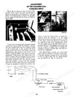
| Cleaning Fan and Variable Drive Area | 50-60 | Disassembly of the Cleaning Fan, Adjustment of the Wind Boards and Wind Deflectors |
| Grain Pan and Shaker Shoe Area | 61-66 | Removal and Installation of the Upper Section of the Cleaning Shoe, Removal and Installation of the Grain Pan, Adjustment of the Cleaning Shoe and Grain Pan |
| Grain and Tailings Elevator Area | 67-79 | Removal and Installation of the Tailings Elevator Chain, Disassembly and Reassembly of the Tailings Elevator Top Shaft |
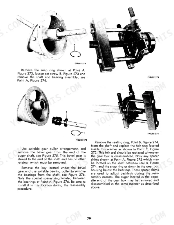
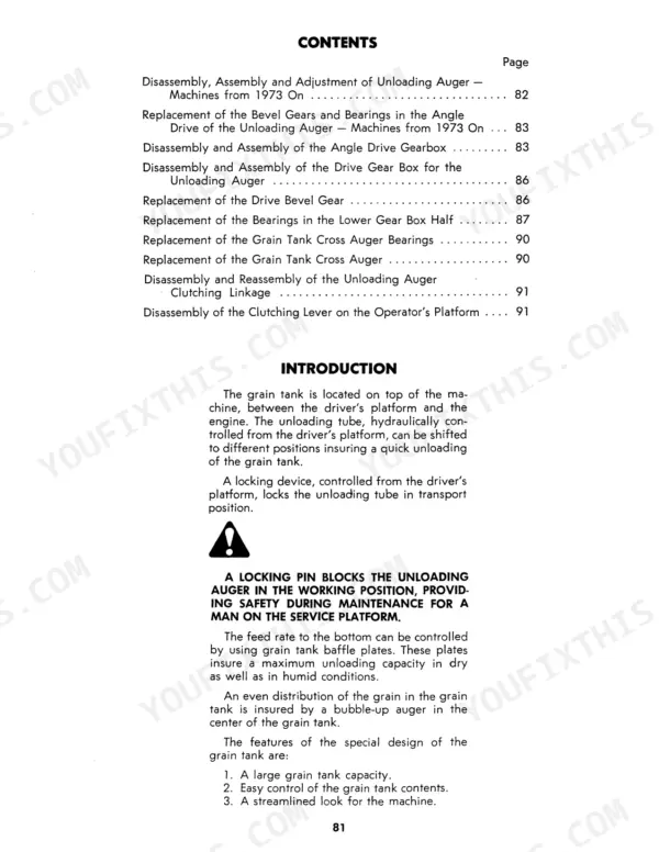
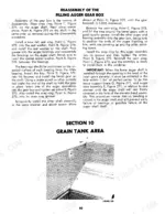
| Grain Tank Area | 80-91 | Disassembly, Assembly and Adjustment of Unloading Auger, Disassembly and Assembly of the Angle Drive Gear Box |
| Steering and Rear Axle Area | 92-100 | Replacement of the Steering Column Bearings, Disassembly and Assembly of a Spindle and the Spindle Bushings |
| Clutch and Transmission Area | 101-126 | Disassembly, Assembly and Adjustment of the Clutch, Disassembly and Assembly of the Differential and Gears, Removal and Re-Installation of the Transmission Gears |
| Brakes and Parking Brake Area | 127-134 | Disassembly and Assembly of the Parking Brake System, Disassembly and Assembly of the Brake Discs |
| Ground Speed Vari-Drive Area | 135-142 | Removal of the Sheave Fork, Variator Adjustments |
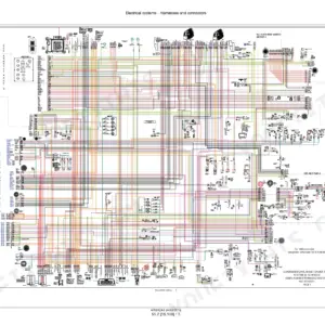
| Hydraulic System | 143-168 | Disassembly and Reassembly of the Hydraulic Pump, Disassembly and Reassembly of the Steering Hand Pump, Disassembly and Reassembly of the Three-Spool Control Valve |
| Electrical System | 169-178 | Battery |
| Special Tools | 179-182 | Bearing Removal Tools, Gib Key Removal Tools, Clutch Adjustment Tools, Transmission Bearing Tools, Straw Shaft Alignment Tools |
| Engine Area | 183-190 | Ford Industrial Gas Engines, Ford Industrial Diesel Engines, Caterpillar Diesel Engines, Engine Specifications, Engine Maintenance Manuals |
Quick Reference Specifications
| Specification | Value | Page |
|---|---|---|
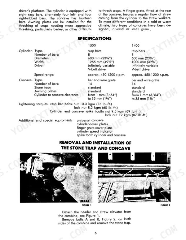
| rasp bar bolts: nut | 10.3 kgm (75 lb.-ft.) | p. 5 |
| rasp bar bolts: lock nut | 8.2 kgm (60 lb.-ft.) | p. 5 |
| Cylinder to concave clearance | 1 mm (3/64”) to 35 mm (1 3/8”) | p. 5 |
| Cylinder drive belt deflection | 5 millimeters (3/16”) | p. 11 |
| Distance between the frame of the combine and the center line of the sheave | 60 mm (3 3/8") | p. 21 |
| Distance from end of the shaft up to the bearing housing | 320 mm (12 5/8") | p. 22 |
| 1500 Straw Walker Width | 1285 mm (50-19/32") | p. 41 |
| 1500 Straw Walker Length with extension | 3800 mm (149-39/64") | p. 41 |
| Rubber bushing compression | 35 mm (1 3/8") | p. 91 |
| Pump bolt torque | 25 ft. lb. | p. 149 |
| Cylinder Diameter | 600 mm | p. 5 |
| Cylinder Width | 1255 mm | p. 5 |
New Holland 1400, 1500 Common Problems This Manual Covers
New Holland 1400 and 1500 combine cylinder slugs in tough straw, cracked grain and unthreshed heads in the tank
Cylinder to concave clearance ranges from 1 mm (3/64 in) to 35 mm (1 3/8 in) (page 5). With the control lever in the second position, the distance between the cylinder and both the first and tenth concave bars should be 10 mm (13/32 in); for tough threshing conditions set a front-to-rear wedge with the lever in notch #1, 8 mm at the second concave rub bar and 1.5 mm at the ninth (page 7). Awning plates can be installed for crops needing more aggressive threshing, particularly barley (page 5).
Manual Section: Cylinder and Concave Area p. 7Cylinder drive belt squeals and slips under heavy feeding, cylinder speed drops in the crop
The cylinder belt tension is correct when the belt deflects 5 millimeters (3/16 in) with a 32-pound pull applied midway between the drive and driven sheaves. To tighten it, loosen the three bolts at point B with cap screw C on the right-hand side of a lug to prevent over-tightening, then start the engine and engage the thresher clutch so the outer sheave half turns on its left-hand threads; repeat, moving bolt C to the opposite hole, until the tension is correct (page 11).
Manual Section: Cylinder Drive Belt Adjustment p. 11Intermediate shaft bearing runs hot and squeals, vibration through the thresher drive at full throttle
When fitting a new intermediate shaft bearing, tap the bearing onto the shaft until there is a 1 mm (3/64 in) space between the bearing housing and the frame, remove the three 1 mm spacer washers and retighten the mounting bolts so the bearing moves 1 mm inside its housing, and fit the spacer ring with its beveled side toward the bearing. Special pullers #327402 and #327406 may be needed to remove the old bearing and housing (page 25).
Manual Section: Intermediate Shaft Area p. 25Hydraulic pump noisy with foaming oil, header lifts slowly and hydraulic oil overheats
The pump troubleshooting table on page 150 lists, for foaming oil, low oil level (fill the reservoir), air leaking into the suction line (tighten fittings) and the wrong kind of oil (refill with non-foaming oil); for a noisy pump, cavitation from low oil supply, oil too heavy, a plugged oil filter or a plugged or undersized suction line; for oil heating, low supply, contaminated oil, a relief valve set too high or too low, or oil too light. On reassembly, draw the pump bolts up evenly to 25 ft. lb. and test the rebuilt pump for three minutes each at zero, 500, 1000 and 2000 p.s.i. (page 149).
Manual Section: Hydraulic System p. 150Traction clutch slips under load, combine loses ground speed pulling into heavy crop on hills
On the 1500 clutch a new clutch disc is 8 mm thick, and the pressure plate springs should be yellow; springs that have turned black-grey have overheated and must be replaced (page 104). After shimming the thrust levers, the maximum height difference between the adjusting screws is 0.3 millimeter (1/64 in), and the pressure plate mounting bolts are tightened to 22 ft. lbs. (page 105).
Manual Section: Clutch and Transmission Area p. 104Frequently Asked Questions
What is the tightening torque for the cylinder rasp bar bolts on the New Holland 1400 and 1500 combines?
The tightening torque for the rasp bar bolts is 10.3 kgm (75 lb.-ft.) for the nut and 8.2 kgm (60 lb.-ft.) for the lock nut. p. 5
What is the cylinder-to-concave clearance range on the New Holland 1400 and 1500 combines?
The cylinder to concave clearance should be adjusted from 1 mm (3/64") to 35 mm (1 3/8"). p. 5
What is the correct cylinder drive belt tension on the New Holland 1400 and 1500 combines?
The cylinder belt tension is correct when the belt can be deflected 5 millimeters (3/16") with a 32-pound pull, applied midway between the drive and driven sheaves. p. 11
What is the intermediate shaft speed on the New Holland 1400 and 1500 combines?
The intermediate shaft speed should be 780 R.P.M. for gasoline engines and 760 R.P.M. for diesel engines. p. 17
What is the thresher clutch spring compressed length on the New Holland 1400 and 1500 combines?
When engaging the control lever, the thresher clutch spring should be tightened until the compressed length is 100 mm (3 15/16"). p. 33
Will this New Holland 1400 Service Manual download right away?
Delivery is instant: a 190-page searchable PDF is yours the second checkout clears. Laptop, tablet, or phone, all fine.
Is this New Holland 1400 Service Manual printable?
No restrictions at all. Print individual pages, full chapters, or the entire manual. The PDF is completely unlocked.






Reviews
There are no reviews yet.