
Part of the New Holland Repair Manuals.
This is the factory repair manual New Holland issued for the CS520, CS540, CS640, CS660 and CL560 straw walker combines. The biggest section by far is Crop Processing: feeder housing, threshing drum and concave, straw walker separation, cleaning shoe and sieves, grain tank and unloading, straw chopper and residue spread. Around that sit a full engine chapter with torque tables (cylinder head bolts go in two stages, 55 Nm then 95 Nm), hydraulic pump pressure and flow specs (main pump 280 bar / 48 l/min), hydrostatic drive test procedures, and an electronic section with a complete E code fault index. Electrical coverage is connector pinout tables with wire numbers, colors and install locations, plus the wire marking format key.
What's Inside This New Holland CS520-CS660 and CL560 Repair Manual
| System | Pages | Key Topics |
|---|---|---|
| Primary Hydraulic Power System | 32-75 | Main Hydraulic Pump, Steering Pump, Lateral Flotation Pump, Pressure and Flow Specifications, Filters and Reservoir |
| Pneumatic System | 80-126 | Compressor, Air Tanks, Air Actuated Controls, Pressure Regulation |
| Electrical Power System | 131-720 | Connector Pinouts and Wire Harness Routing, Component Installation Locations, Wire Color and Gauge Marking, Battery and Charging Circuit |
| Lighting System | 721-744 | Exterior Lighting, Work Lights, Beacon and Signal Lamps |
| Electronic System | 747-770 | Fault Code Index, Self Leveling Control, Sensors and Control Modules |
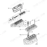
| Engine | 779-842 | Cylinder Block and Head, Crankshaft and Camshaft, Valve Train, Torque Specifications |
| Fuel Injection System | 849-896 | Injection Pump, Injectors, Fuel Filtration, Governor |
| Engine Coolant System | 901-922 | Radiator, Water Pump, Thermostat, Cooling Fan |
| Lubrication System | 925-936 | Oil Pump, Oil Filter, Oil Pressure Regulation |
| Starting System | 939-946 | Starter Motor, Alternator, Battery |
| Power Train | 950-1163 | Transmission of Power, Axles, Hydrostatic Drive, Process Drive Functions |
| Travelling | 1164-1317 | Machine Movement, Tracks, Wheels, Steering, Braking, Axle Suspension |
| Body and Structure | 1318-1441 | Frame, Shields, Operator's Cab, Platform |
| Frame Positioning | 1442-1465 | Ground Clearance Adjustment, Frame Leveling, Positioning Cylinders |
| Tool Positioning | 1466-1693 | Automatic Header Positioning, Header Lift Arm, Header Height Sensor, Reel Height Control |
| Crop Processing | 1694-2443 | Feeding and Threshing, Straw Walker Separation, Cleaning Shoe and Sieves, Grain Tank and Unloading, Straw Chopper and Residue |
Quick Reference Specifications
| Specification | Value | Page |
|---|---|---|
| Hydraulic system | ||
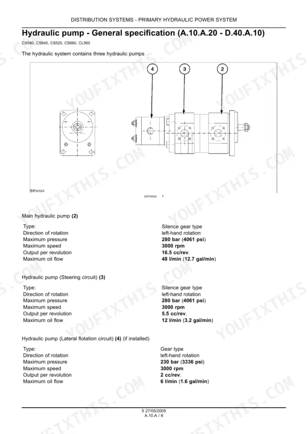
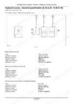
| Main hydraulic pump pressure | 280 bar (4061 psi) | p. 34 |
| Main hydraulic pump flow | 48 l/min (12.7 gal/min) | p. 34 |
| Main hydraulic pump displacement | 16.5 cc/rev | p. 34 |
| Steering pump displacement | 5.5 cc/rev | p. 34 |
| Steering pump flow | 12 l/min (3.2 gal/min) | p. 34 |
| Lateral flotation circuit pressure | 230 bar (3336 psi) | p. 34 |
| High pressure relief valve (main) | 180 bar | p. 49 |
| System pressure limit | 210 bar | p. 50 |
| Engine | ||
| Camshaft gear torque | 69 Nm (51 lb ft) | p. 815 |
| Idler gear torque | 204-279 Nm (150-205 lb ft) | p. 815 |
| Engine plug torque (1) | 8-14 Nm (6-10 lb ft) | p. 822 |
| Engine plug torque (2) | 27-47 Nm (20-35 lb ft) | p. 822 |
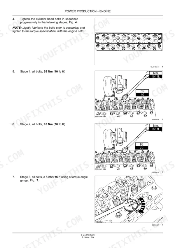
| Cylinder head bolts Stage 1 torque | 55 Nm (40 lb ft) | p. 833 |
| Cylinder head bolts Stage 2 torque | 95 Nm (70 lb ft) | p. 833 |
| Engine fastener torque | 38 Nm (28 lb ft) | p. 835 |
| Crop Processing - Feeding | ||
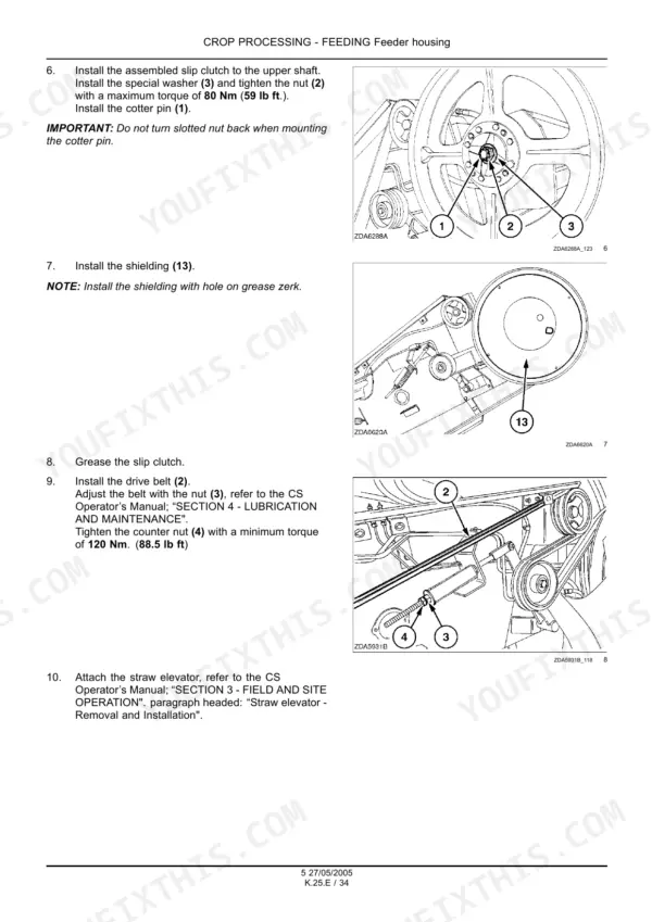
| Feeder slip clutch nut torque (max) | 80 Nm (59 lb ft) | p. 1794 |
| Feeder bottom shaft nut torque (max, both sides) | 28 Nm (20.6 lb ft) | p. 1813 |
New Holland CS520-CS660 and CL560 Common Problems This Manual Covers
Header height control hunts, drops the header, or stops responding in the field
Work the Tool Positioning troubleshooting list in order: connector, harness, header height sensor, then the central controller module. Most of these turn out to be a corroded connector or chafed harness, not the sensor, so test before buying parts.
Manual Section: Tool Positioning - Automatic header positioning / header height sensor p. 1574Hydrostatic drive is sluggish, loses power on slopes, or overheats
Run the hydrostatic pressure test in the Power Train chapter and read it the way the book does: low charge pump inlet vacuum means a suction line or filter screen restriction, abnormal case pressure means return lines, oil cooler or filter. That reading tells you which side to open up first.
Manual Section: Power Train - Hydrostatic drive pressure testing p. 1107Feeder slip clutch ratchets in heavy crop, or slips constantly after someone cranked it down
The feeder section gives hard limits people routinely exceed: slip clutch nut at a maximum of 80 Nm (59 lb ft), feeder bottom shaft nuts at a maximum of 28 Nm (20.6 lb ft) on both sides. Overtightening the clutch just moves the failure into the feeder chains and shafts.
Manual Section: Crop Processing - Feeder housing (feeding and threshing) p. 1794Self-levelling cleaning shoe stops levelling or the monitor throws an E code
Pull the code from the fault index and follow it to the diagnostic entry. E504, for example, is the left hand self-levelling override switch (S26) shorted to ground, so you are checking that switch and its harness with the connector pinout tables, not swapping the module first.
Manual Section: Electronic System - Fault code index and self-levelling control diagnostics p. 750Frequently Asked Questions
The automatic header height control will not hold the cutting height. Does this manual actually help me chase that down?
Yes. The Tool Positioning chapter has a troubleshooting list for header height control failures in a sensible order: faulty connector, faulty harness, faulty header height sensor, faulty central controller module (CCM). You check the cheap stuff before condemning the CCM. It also covers the header lift arm and reel height control. p. 1574
Does it list the fault codes and tell me what they mean?
There is a full fault code index (sections A.50.A through C.40.G.10). Every code is an E number plus a plain English description, for example E504 = self-levelling override switch (S26), left hand side, short to ground. The index points you to the matching diagnostic entry; it is not a one-button reset chart, you follow the code into the diagnostic section and fix the cause. p. 746
What electrical documentation does this manual actually include?
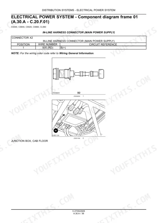
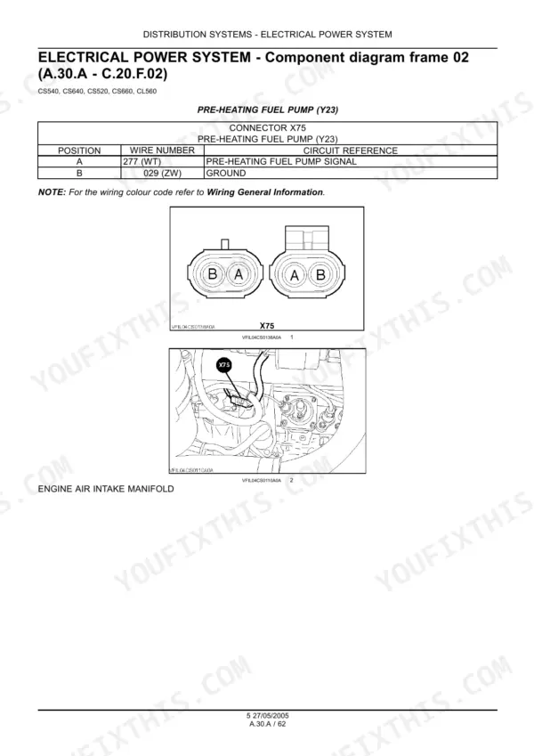
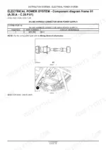
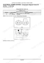
No circuit schematics - the indexed schematic frames in this scan are blank title pages. What you do get is connector pinout tables and a wire marking guide, and for tracing a dead circuit that is usually what you need: for example connector X2 pin 005 (red) is B(+) at the junction box on the cab floor, and every wire is marked number, cross section and color, destination connector and pin. p. 164
I am pulling the head on the engine. Are the torque specs and sequences in here?
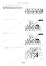
The engine chapter covers cylinder block and head, crankshaft, camshaft and valve train with torque figures throughout. Cylinder head bolts are a two stage tightening: all bolts to 55 Nm (40 lb ft), then all bolts to 95 Nm (70 lb ft). Camshaft gear is 69 Nm (51 lb ft). Do not collapse the head stages into one pull. p. 833
The hydrostatic drive feels weak and runs hot. Is there a real test procedure?
The Power Train chapter has a hydrostatic pressure test with interpretation, not just numbers: a low charge pump inlet vacuum reading points to a restriction in the suction lines or filter screen, abnormal case pressure points to the return lines, oil cooler or filter. Pump specs for the whole hydraulic side (main pump 280 bar, 48 l/min, 16.5 cc/rev) are in the hydraulic chapter. p. 1107






Reviews
There are no reviews yet.