
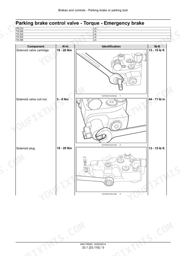
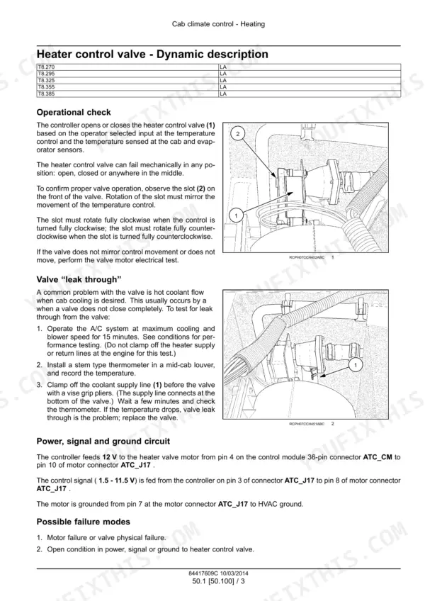
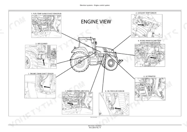
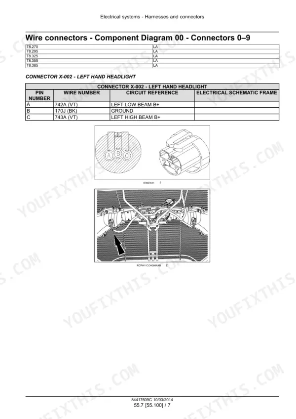
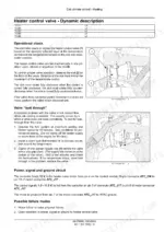
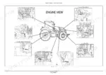
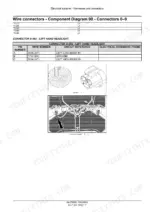
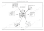
Part of the New Holland Repair Manuals.
Fits the New Holland T8.270, T8.295, T8.325, T8.355 and T8.385, all 18x6 Powershift with cab and the 9.0 l engine. Part number 84417609, in English, dated March 2014, for the Latin America market.
This manual covers the master clutch, speed and range transmission overhaul, Dana and New Holland front axles, differential lock, PTO, brakes, PFC pump hydraulics, rear three-point hitch, steering and cab A/C. It gives test pressures and tightening torques.
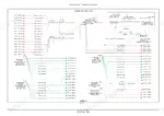
The electrical section is the largest part of the book. It has connector pinouts, fuse and relay boxes, schematic sheets 01 to 89 and the fault code index. Sections are numbered by system, like 21.155 for transmission internals.
What's Inside This New Holland T8.270–T8.385 Series Manual
| System | Pages | Key Topics |
|---|---|---|
| Introduction and Specifications | 1-20 | Model Applicability, Product and Engine Identification, Safety Rules, International Symbols, Fluid Capacities |
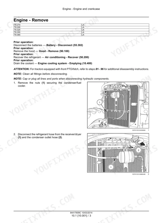
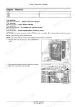
| Engine | 21-182 | Engine Removal and Installation, Valve Clearances, Cylinder Heads, Pump Drives, Air Cleaners, Fuel Tanks, Aftercooler, Cooling System |
| Power Coupling | 183-190 | Engine-To-Drop-Box Drive Shaft, Coupler Shields, Coupler Alignment, Mounting-Bolt Tightening |
| Powershift Transmission - Controls and Testing | 191-327 | Regulated-Pressure Accumulator, Transmission Torques, Forward/Reverse Gear Operation, Creeper, Leakage Tests, Troubleshooting, Inching Valve, Control Valves |
| Powershift Transmission - Internal Components and Drop Box | 328-594 | Master Clutch, Shaft Assemblies, Clutch Spring Limits, Bearing Adjustment, Speed and Range Transmission Overhaul, Drop Box Gears, Splitting and Joining |
| Four-Wheel Drive (4WD) System | 595-664 | Electro-Hydraulic Control, MFD Clutch, Clutch Brake, Drive Shaft Removal and Installation |
| Front Axle System | 665-996 | Dana and New Holland Front Axles, Bevel Gears, Differential, Final Drive Hubs, Steering Knuckles, King Pins, Shaft Seals |
| Rear Axle System | 997-1136 | Powered Rear Axle, Bevel Pinion, Differential, Differential Lock, Planetary Final Drives |
| Power Take-Off (PTO) | 1137-1396 | Rear Electro-Hydraulic Control, PTO Control Valve, One-Speed and Two-Speed Rear PTO, PTO Clutch Testing, Front PTO |
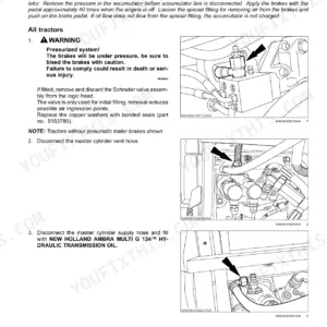
| Brakes and Controls | 1397-1534 | Emergency-Brake Accumulator, Parking-Brake Control Valve, Park Clutch, Three-Disc Brake, Hydraulic Service Brakes, Brake Pressure Tests |
| Hydraulic Systems | 1535-1790 | Hydraulic Schematics and Symbols, Priority/Regulator Valve, PFC Pumps, Flow and Pressure Tests, Hitch Control Valve, Remote Valves, Reservoirs and Filters |
| Pneumatic System | 1791-1802 | Air Compressor Removal and Installation, Air Inlet and Outlet Connections, Coolant Fittings |
| Hitches, Drawbars and Implement Couplings | 1803-1830 | Rear Three-Point Hitch Removal, Disassembly, Assembly and Installation |
| Steering | 1831-1872 | Steering Control, Steering Cylinders, Hydraulic Control Components, Steering Pump |
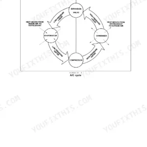
| Cab Climate Control | 1873-2014 | Cab Heating, Refrigerant Recovery and Charging, Circuit Flushing, Compressor, Expansion Valve, A/C Diagnosis, Cab Pressurizing Filters |
| Electrical - Fan Drive, Engine, Transmission and Axle Controls | 2015-2099 | Vistronic Fan Drive, Engine Control, Transmission Control, Front Axle Sensors, Differential Lock Control, HVAC Sensors and Testing |
| Electrical - Harnesses, Connectors, Fuses and Relays | 2100-2472 | Connector Diagrams and Pin Identification, Harness Interfaces, Fuse and Relay Identification, Rear Cab Fuse/Relay Boxes |
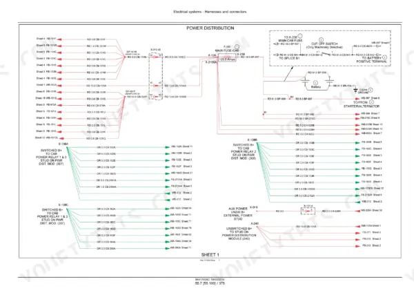
| Electrical - Wiring Schematic Sheets 01-89 | 2473-2661 | Power Distribution, Starting and Charging, Electronic Engine, Transmission Control, Lighting, Hitch Control, CAN Buses, Secondary Steering |
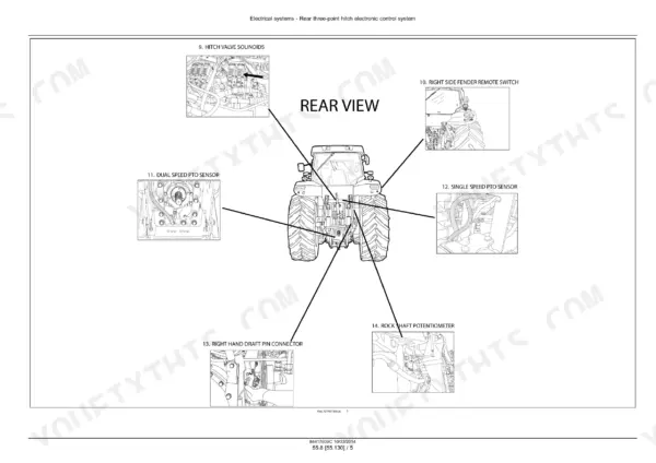
| Electrical - Hitch, Starting and Calibration Procedures | 2662-2765 | Hitch Sensors, Engine Starting System, Battery Disconnection, Fault-Code Retrieval, Transmission, EDC, EHR Valve and Ground-Speed Calibration |
| Fault Codes (DTC) | 2766-2788 | Fault Code Index, Front Suspension, Hitch Control, Transmission and Engine-Control Messages |
| Platform, Cab, Bodywork and Decals | 2789-2941 | Engine Hood, Latches and Shields, Operator Seat, Cab Removal and Installation, Cab Interior Trim and Panels |
| Special Tool Index | 2942-2949 | Torque-Angle Tools, Clutch Compressors, Axle and Differential Tools, Refrigerant Recovery and Calibration Tools |
Quick Reference Specifications
| Specification | Value | Page |
|---|---|---|
| Engine oil capacity, no filter change | 24.0 L (6.3 US gal) | p. 18 |
| Engine oil capacity, with filter change | 27.0 L (7.1 US gal) | p. 18 |
| Cooling system capacity | 26.5 L (7.0 US gal) | p. 18 |
| Transmission system, hydraulic system and brakes capacity | 174.0 L (46.0 US gal) | p. 18 |
| Fuel tank capacity | 636.0 L (168.0 US gal) | p. 18 |
| Front axle differential capacity (heavy duty class 5 axle) | 15.0 L (15.9 US qt) | p. 18 |
| Front axle planetary capacity, each (heavy duty class 5 axle) | 6.0 L (12.7 US pt) | p. 18 |
| Intake valve clearance | 0,40 mm | p. 70 |
| Exhaust valve clearance | 0,60 mm | p. 70 |
| Regulated-pressure accumulator nitrogen charge pressure | 9.7 - 10.3 bar (141 - 150 psi) | p. 194 |
| Emergency-brake accumulator nitrogen charge pressure | 9.3 bar (135 psi) | p. 1401 |
| Priority regulator valve regulated pressure | 22.4 - 24.5 bar (325 - 355 psi) | p. 1579 |
| PFC pump low-pressure standby | 24.1 - 27.5 bar (350 - 400 psi) | p. 1659 |
| Charge/lubrication pump flow at 2820 RPM pump (2000 RPM engine) | 187.0 l/min (49.0 US gpm) | p. 1579 |
| Cooling/filtration/auxiliary charge pump flow at 2820 RPM pump (2000 RPM engine) | 105.0 l/min (27.5 US gpm) | p. 1579 |
| Standard PFC pump maximum flow at 2820 RPM pump (2000 RPM engine) | 177.0 l/min (46.5 US gpm) | p. 1579 |
| Optional high flow PFC pump maximum flow at 2820 RPM pump (2000 RPM engine) | 239 l/min (63 US gpm) | p. 1580 |
| Optional Megaflow PFC pump maximum flow at 2820 RPM pump (2000 RPM engine) | 124 l/min (32.7 US gpm) | p. 1580 |
| One-speed rear PTO speed sensor tightening torque | 16 - 22 Nm (12 - 16 lb ft) | p. 1180 |
| One-speed rear PTO output-shaft housing bolts tightening torque | 90 - 100 Nm (66 - 74 lb ft) | p. 1179 |
New Holland T8.270–T8.385 Series Common Problems This Manual Covers
Tractor does not move after a master clutch or range transmission repair, even though master clutch pressure is within specifications.
This is a reassembly mistake. The master clutch was indexed incorrectly on the shaft. Since the pressure reads correctly, the fault is mechanical, not hydraulic. The manual sends you to Master clutch - Disassemble (21.155) to take it back apart and correct the indexing.
Manual Section: Powershift transmission - Troubleshooting p. 286Tractor has three sets of 1-6 gears/shift speeds after a range transmission repair.
The medium/high clutch went back on the shaft incorrectly indexed during the range transmission rebuild. The tractor still drives, but the shift pattern is wrong. The printed reference is Shaft assemblies Range input shaft - Disassemble (21.155), in the Powershift transmission internal components section.
Manual Section: Powershift transmission - Troubleshooting p. 286Tractor moves in reverse when shifted into 5th, 6th, 11th or 12th gear after a speed transmission repair.
The reverse/5th clutch hub was installed backward on the shaft when the speed transmission was reassembled. The manual covers the correction under Output shaft - Disassemble (21.155), in the Powershift transmission internal components section.
Manual Section: Powershift transmission - Troubleshooting p. 286Odd gears are even and even gears are odd after a speed transmission repair.
The odd/even clutch was installed backward during speed transmission reassembly. The manual's reference is Shaft assemblies Speed counter shaft - Disassemble (21.155). It has separate procedures for tractors with the creep option and without it, so follow the one that matches your build.
Manual Section: Powershift transmission - Troubleshooting p. 286Frequently Asked Questions
Which tractors does the New Holland T8.270-T8.385 service manual cover?
It covers the T8.270, T8.295, T8.325, T8.355 and T8.385. Each one is listed as 18x6 Powershift with cab, Latin America market. The part number is 84417609, dated March 2014. The applicability list doesn't print an upper serial limit. p. 2
How much engine oil and coolant does a New Holland T8.270, T8.295, T8.325, T8.355 or T8.385 take?
Engine oil is 24.0 L (6.3 US gal) without a filter change, or 27.0 L (7.1 US gal) with a new filter. The cooling system holds 26.5 L (7.0 US gal). Both figures are in the fluid capacities table in the introduction section. p. 18
What is the fuel tank and transmission/hydraulic system capacity of the New Holland T8 series?
The fuel tank holds 636.0 L (168.0 US gal). The transmission system, hydraulic system and brakes are listed together at 174.0 L (46.0 US gal). p. 1579
What are the PFC hydraulic pump flow rates on the New Holland T8.270-T8.385?
These are maximum flows at rated speed, which is 2820 RPM at the pump or 2000 RPM at the engine. The standard PFC pump delivers 177.0 l/min (46.5 US gpm). The optional high flow pump is listed at 239 l/min (63 US gpm), and the optional Megaflow pump at 124 l/min (32.7 US gpm). The manual notes that the two PFC pump hydraulic circuits operate independently. p. 1579
Does the New Holland T8.270-T8.385 service manual include wiring diagrams, hydraulic schematics and fault codes?
Yes, it has all three. Electrical schematic sheets 01 to 89 start at p.2473, including sheet 01 Power distribution and sheet 07 Starting/charging system. Hydraulic schematics for Powershift tractors start at p.1539. The fault code index begins at p.2768, with entries like 10006 Front suspension will not raise and 10022 12VM voltage supply low. p. 2768






Reviews
There are no reviews yet.