

Part of the New Holland Repair Manuals.
This is the factory service manual, publication 87725889C, for the New Holland CR9060, CR9060/CR9070/CR9080/CR9090 Elevation, CR9080 and the CX8030 through CX8090 combines, dated 14/01/2010. Inside you get the full hydraulic story (primary, secondary and command systems with real test pressures like 207 bar max system and 21 bar standby), hundreds of pages of electrical schematic frames and wiring harness component diagrams, hydrostatic and mechanical drivetrain teardown, feeder, threshing, separating, cleaning and unloading service, plus the fault code index on page 1601. Two honest limits, printed in the book itself: internal engine overhaul lives in the engine maker's own manual, and step by step Fault Code Resolution is not in this version, only the index.
What's Inside This New Holland CR9060-CR9090, CX8030-CX8090 Manual
| System | Pages | Key Topics |
|---|---|---|
| Introduction and General Information | 1-16 | Safety Precautions, Standard Torque Data, Rotating Shaft Seal Installation, Welding and Battery-Charging Precautions |
| Primary Hydraulic Power System | 17-66 | CCLS Main Pump, High-Pressure Circuit, Header Suspension and Lateral Float Accumulators, Pressure Testing |
| Secondary Hydraulic Power System | 67-92 | Secondary Pump, Hydraulic Pump Torque Data, Circuit Static Description |
| Hydraulic Command System | 93-100 | Stack Valve Removal and Installation, Command Circuit Service |
| Pneumatic System | 101-126 | Compressor, Air Reservoir, Pneumatic Circuit Service |
| Electrical Power System - Technical Data, Symbols and Component Location | 127-355 | Electrical Standards, Wiring Colour Code, Electrical Symbols, Component Localisation and Identification, Special Tools |
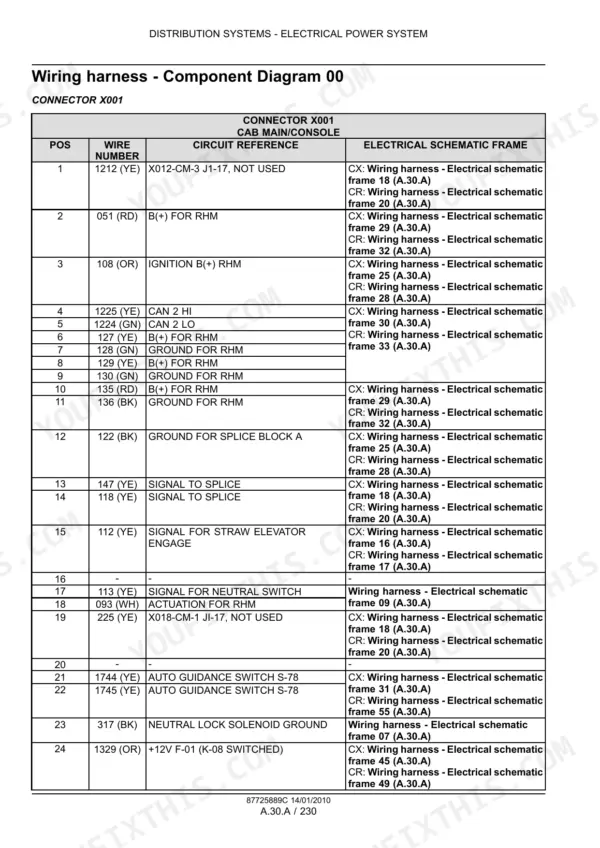
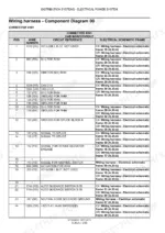
| Electrical Power System - Wiring Harness Component Diagrams | 356-849 | Connector-By-Connector Diagrams X001 Onwards, Pin Positions, Wire Numbers, Circuit References |
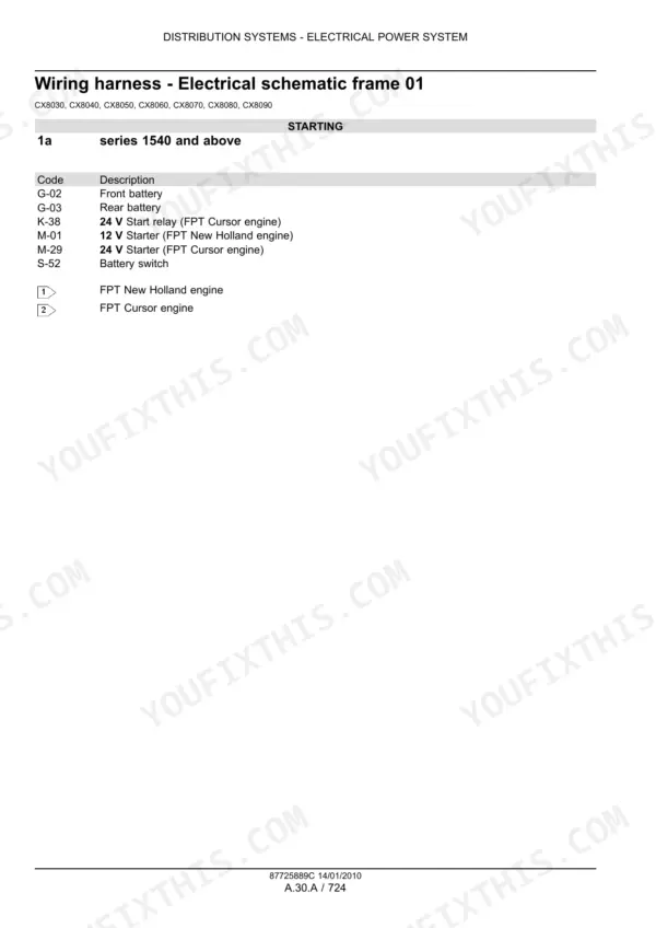
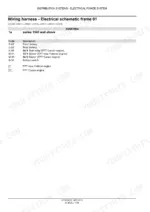
| Electrical Power System - Electrical Schematic Frames | 850-1437 | Full Circuit Schematic Frames for the CR and CX Series, Starting, Lighting, Control Modules |
| Electrical Power System - Preliminary Tests, Service and Diagnostics | 1438-1472 | Multimeter Preliminary Tests, Alternator Drive Belt Tensioner, Wiring Harness Repair, Fuse and Relay Box Problem Solving |
| Lighting System | 1473-1532 | Work Lights, Road Lighting, Beacon, Lamp Service |
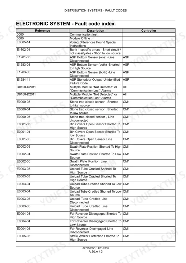
| Electronic System and Fault Code Index | 1533-1622 | Fault Code Index in E####-## Format, Controller List, Active-Error Display, Module Communication |
| Power Production - Engine, Fuel and Injection, Air Intake, Exhaust, Coolant, Starting | 1623-1710 | Engine, Fuel Shut-Off Solenoid, Air Intake, Exhaust, Coolant Capacities, Rotary Screen, Radiator Testing, Starting System |
| Power Train - Power Coupling and Mechanical Transmission | 1711-1792 | Fixed Coupling, Mechanical Gearbox Service |
| Power Train - Hydrostatic Transmission | 1793-1926 | H1 Series Pump, Multifunction Valve, High-Pressure Relief and Charge Check, Hydrostatic Motor |
| Power Train - Primary Process Drive | 1927-1984 | Primary Process Drive Belts, Pulleys and Clutch Service |
| Travelling - Front and Rear Axles, 2WD-4WD Hydrostatic System, Steering, Brakes | 1985-2180 | Front and Rear Axle, 2WD-4WD Hydrostatic Drive, Hydraulic and AutoPilot Steering, Service and Parking Brakes |
| Body and Structure - Shields, Operator Platform, User Controls and Seat | 2181-2276 | Shields, Operator and Service Platform, User Controls, Operator Seat |
| Body and Structure - Heating, Air-Conditioning and Safety Accessories | 2277-2430 | Heating System, Air-Conditioning, HVAC, A/C Line Torque Table, Safety Accessories |
| Tool Positioning - Header Lifting and Levelling | 2431-2454 | Header Lifting, Automatic Levelling |
| Crop Processing - Header Feeding, Feeder Housing and Threshing | 2455-2896 | Header Feeding, Feeder Housing, Rotor Feeding, Conventional and Twin-Flow Threshing, Rasp Bar Replacement |
| Crop Processing - Separating, Grain Storing and Cleaning | 2897-3260 | Beating, Rotary Separator, Twin-Flow Rotor, Straw Walker, Straw Flow and Discharge Beaters, Grain Storing, Primary Cleaning, Tailings Return |
| Crop Processing - Residue Handling, Grain Unloading and Protection Systems | 3261-3528 | Straw Chopper, Spreader, Chaff Blower and Spreader, Positive Straw Discharge, Grain Unloading, Reversing System, Stone Trap |
Quick Reference Specifications
| Specification | Value | Page |
|---|---|---|
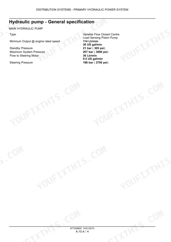
| Main hydraulic pump minimum output at engine rated speed | 114 l/min (30 US gal/min) | p. 20 |
| Main hydraulic pump standby pressure | 21 bar (305 psi) | p. 20 |
| Main hydraulic pump maximum system pressure | 207 bar (3000 psi) | p. 20 |
| Steering pressure | 186 bar (2700 psi) | p. 20 |
| High pressure relief valve setting | 197 bar (2856 psi) | p. 36 |
| High pressure relief valve setting (secondary) | 220 bar (3190 psi) | p. 36 |
| Header suspension accumulator pressure | 70 bar (1015 psi) | p. 36 |
| Lateral float minimum pressure valve setting | 60 bar (870 psi) | p. 31 |
| High hydraulic oil temperature indication | 85 °C (185 °F) | p. 33 |
| Engine coolant capacity | 50 - 60 l (13.2 - 15.9 US gal) | p. 1627 |
| Engine oil capacity | 29 - 35 l (7.7 - 9.2 US gal) | p. 1627 |
| Rotary screen motor relief valve pressure | 170 bar (2465 psi) | p. 1672 |
| Radiator tightness test pressure | 0.98 bar (14.21 psi) | p. 1675 |
| Fuel shut-off solenoid rated voltage | 12 V | p. 1651 |
New Holland CR9060-CR9090, CX8030-CX8090 Common Problems This Manual Covers
Electronics act up or modules fail after welding on the machine or jump charging the batteries.
Follow the charging and welding precautions on page 9-10 in the Introduction chapter before any of that work: disconnect the right connections first so welding current and charging spikes never reach the modules. Then use the preliminary tests on page 1438 to confirm what survived.
Manual Section: Introduction and general information / Electrical power system - preliminary tests, service and diagnostics p. 9Chronic oil leaks reappear at shafts and housings that were just rebuilt.
Nine times out of ten it is seal installation, not the seal. Page 9 in the Introduction covers rotating shaft seal installation and shimming practice: shaft surface prep, seal orientation and measured shim stacks. Redo the joint by that procedure instead of just throwing another seal at it.
Manual Section: Introduction and general information p. 9Travel speed faults on the display, sluggish or no machine movement from the hydrostatic drive.
Look the code up in the fault code index on page 1601, then work the hydrostatic transmission chapter: pump and motor testing, charge pressure checks and the speed sensor circuits, backed by the schematic frames for the sensor wiring. That separates a real hydrostatic problem from a sensor or harness fault before you pull anything heavy apart.
Manual Section: Power train - hydrostatic transmission p. 1793Header height control, lateral float or reel functions drift, drop or throw electrical faults.
Use the header lifting and levelling chapter together with the hydraulic command system section: check the suspension accumulator charge at 70 bar and the lateral float minimum pressure valve at 60 bar, then trace the position sensor and valve circuits through the wiring diagrams if the hydraulics test good.
Manual Section: Tool positioning - header lifting and levelling p. 2431Frequently Asked Questions
Does this manual explain New Holland CR/CX fault codes like E1602-04 or the 0000 module offline message?
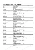
It has the fault code index on page 1601 in the Electronic System chapter: every code in E####-## format plus the bare 0000, with its description and which controller sets it. So E1602-04 reads out as a Bank 1 short circuit to low source, and 0000 means communication lost / module offline. Be clear on the limit though: the book states that step by step Fault Code Resolution (FCR) is not contained in this version, that lives in the Electronic Service Tool or the electronic FCR data. What you get here is the index to identify the code, plus the wiring diagrams, component locations and preliminary multimeter tests (page 1438) to chase it by hand. p. 1601
Will this cover a full engine rebuild on my CX8080 or CR9090?
No, and the manual says so itself on page 8: engine repair information is not in this book, you need the repair manual for the specific engine fitted. What the Power Production chapter does cover is everything around the engine on the machine: fuel system and injection, air intake, exhaust, cooling (coolant capacity 50 to 60 l), starting system including the 12 V fuel shut off solenoid, and engine removal and installation. For a combine that cranks but will not run, that chapter is usually where the answer is anyway. p. 8
Are the wiring diagrams actually usable for tracing a sensor offline or short circuit fault?
Yes, this is the strongest part of the book. You get full electrical schematic frames covering every circuit, a separate section of wiring harness component diagrams showing each harness with connector views, plus component location drawings and symbol keys so you can find the physical part on the machine. Start with the preliminary multimeter tests on page 1438, pull the code description from the index on 1601, then follow that circuit through the schematic frame to the connector. That is exactly how you run down an E1281-05 line disconnected type fault without guessing. p. 850
Does it give real hydraulic test specs, or just theory?
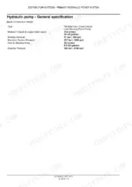
Real numbers you can put a gauge on. Main pump minimum output 114 l/min at rated speed, standby pressure 21 bar, maximum system pressure 207 bar, steering at 186 bar. Relief valve settings of 197 and 220 bar, header suspension accumulator charge 70 bar, lateral float minimum pressure valve 60 bar, and the high oil temperature warning point at 85 degrees C. Between the primary, secondary and command system chapters you can test, diagnose and reset the whole hydraulic side to factory settings. p. 20
Is there a parts catalogue with part numbers in this manual?
No, there is no separate parts catalogue in this document, it is a service and repair manual. What it does give you is component identification through the wiring harness diagrams, hydraulic circuit descriptions and section drawings, which is usually enough to name the part before you call the dealer with your serial number. For ordering, use the New Holland parts system for your specific serial break. p. 2






Reviews
There are no reviews yet.