

Part of the New Holland Repair Manuals.
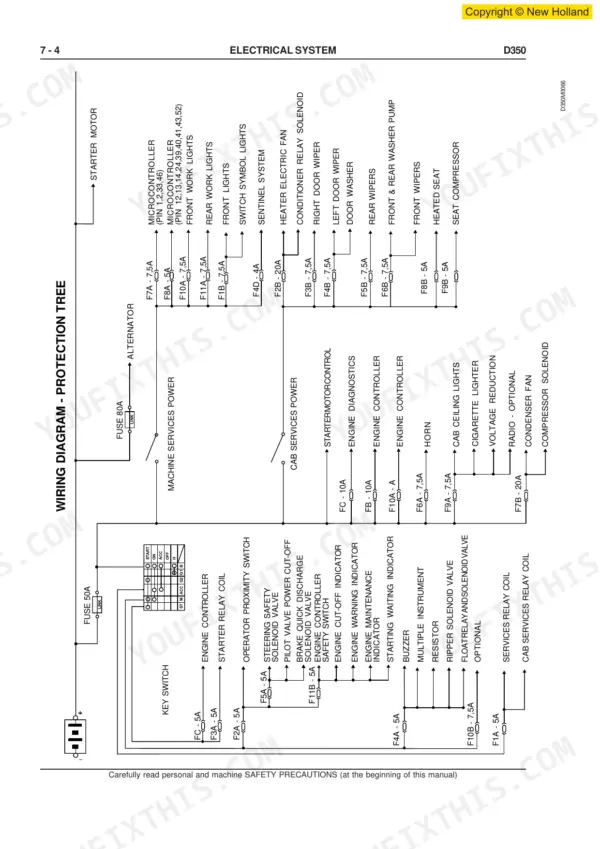
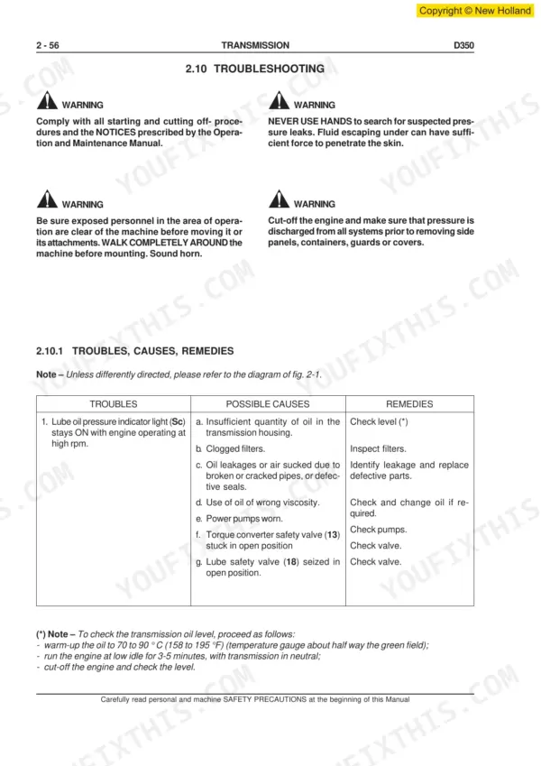
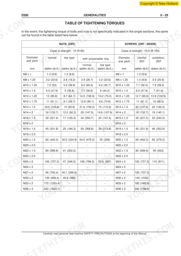
This 348-page New Holland D350 Crawler Dozer Workshop Manual (OEM #604.13.532.00) walks you through every system on the 2005 D350, from the Cummins QSM11 engine down to the final drives. Inside you get full protection tree wiring diagrams, the dozing equipment hydraulic system schematic, and a troubleshooting section covering the converter-transmission group, brake and steering diagnosis display, and undercarriage wear checks. Open to the torque tables and you get real numbers: intake valve clearance at 0.36 mm, exhaust at 0.69 mm, and NBR O-rings rated for continuous duty from -40 to 120°C. No more guessing whether that seal will hold up in your climate or chasing a wiring fault with a test light and a hunch. This PDF carries bookmarks straight to each system, Engine, Transmission, Final Drives, Electrical, so you jump right to the section you need, pull it up on a tablet at the machine, and get your D350 back to work.
What's Inside This New Holland D350 Manual
| System | Pages | Key Topics |
|---|---|---|
| Workshop Manual | 1-2 | Important Notice, Avoid Accidents, Warning |
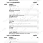
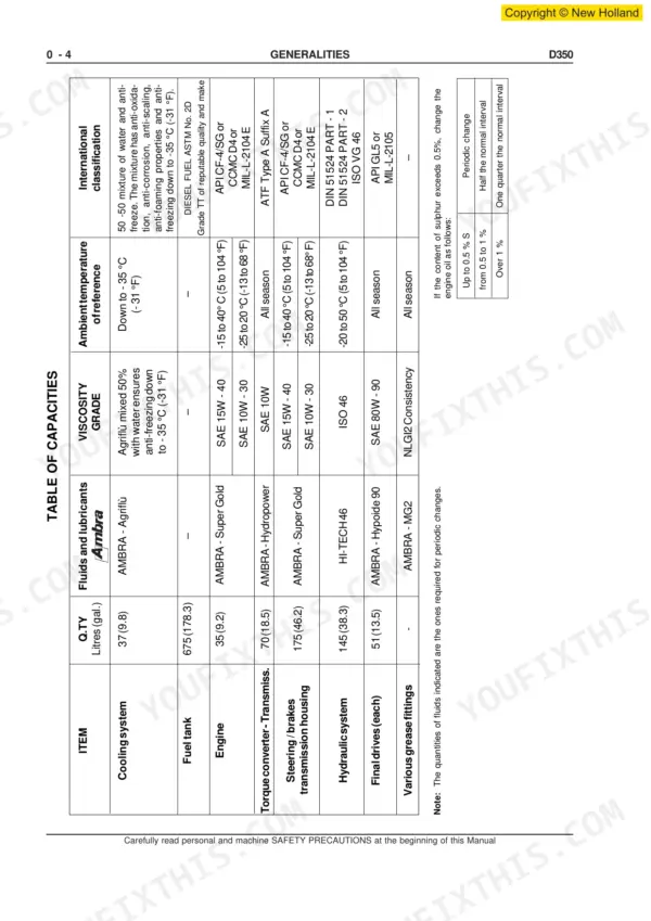
| Generalities | 5-43 | Safety Rules, Table of Technical Data (Identification Data, Table of Capacities, Main Dimensions D350, Specifications D350), Control Data on the Machine |
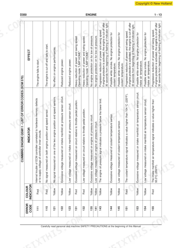
| Engine | 44-62 | General Specifications, Series Qsm 11 Engine Data, Diagrams of Series Qsm 11-C Engine, Mounting of Engine on Frame, Diagnostics for Cummins Engines QSM11 |
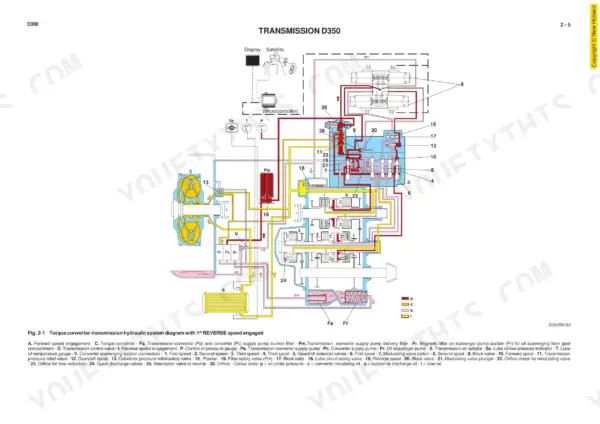
| Transmission | 63-132 | Operation of Converter-Transmission Hydraulic System, Hydraulic Torque Converter, Converter-Transmission Oil Filters, Converter, Transmission-Converter |
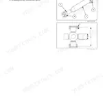
| Final Drives | 133-162 | Repair Procedures (Final Drive, Installation of Front Seals), Specifications and Data (Final Drive Shaft and Bearing Fittings), Special Tools |
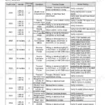
| Brakes and Steering Differential | 163-261 | Failure Diagnosis (Diagnosis Display) |
| Undercarriage | 262-294 | Troubleshooting, Inspections (Adjustment of Track Chains) |
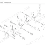
| Dozing Equipment Hydraulic System | 295-320 | Tests (Flow Test in Single Circuits), Repair Procedures (Hydraulic Oil Reservoir, Equipment Hydraulic Pump, Hydraulic Control Valve, Installation of Blade) |
| Electrical System | 321-348 | Safety Rules, Protection Tree Wiring Diagram (Fuses, Link Fuses and Cold Starting, Main Switch, Engine Starter Switch, Back-Up Alarm, Starter Motor) |
Quick Reference Specifications
| Specification | Value | Page |
|---|---|---|
| O-Rings - Field of application - NBR - Temperature of operation | - 40 to 120°C (- 40 to 248°F) | p. 39 |
| O-Rings - Field of application - FPM - Temperature of operation | - 40 to 200°C (-40 to 392°F) | p. 39 |
| Valve clearance Intake | 0.36 mm (0.014 in) | p. 48 |
| Valve clearance Exhaust | 0.69 mm (0.027 in) | p. 48 |
| Clutch disengagement spring (10, fig. 2-69): length of spring under a load of 141 daN | 45 mm (1.771 in) | p. 32 |
| Torque Converter Safety Valve (fig. 2-98) Valve pressure setting | 10 to 11 bar (145 to 159.5 psi) | p. 48 |
| Torque Converter Safety Valve (fig. 2-98) Pressure variation for each shim | 0.7 bar | p. 301 |
| Torque for 20 screws M30 x 2 on top of sprocket support | 186 daNm (1371.4 lb.ft.) | p. 148 |
| Pressure relief valve setting | 22.5 ÷ 27.5 bar | p. 187 |
| Torque for hydraulic motor mounting screws M20 x 50 | 54 daNm | p. 257 |
| Engine Oil Capacity | 35 L | p. 18 |
| Final Drives Oil Capacity (each) | 51 L | p. 18 |